User Manual AMETEK Programmable Power
RS Series 46
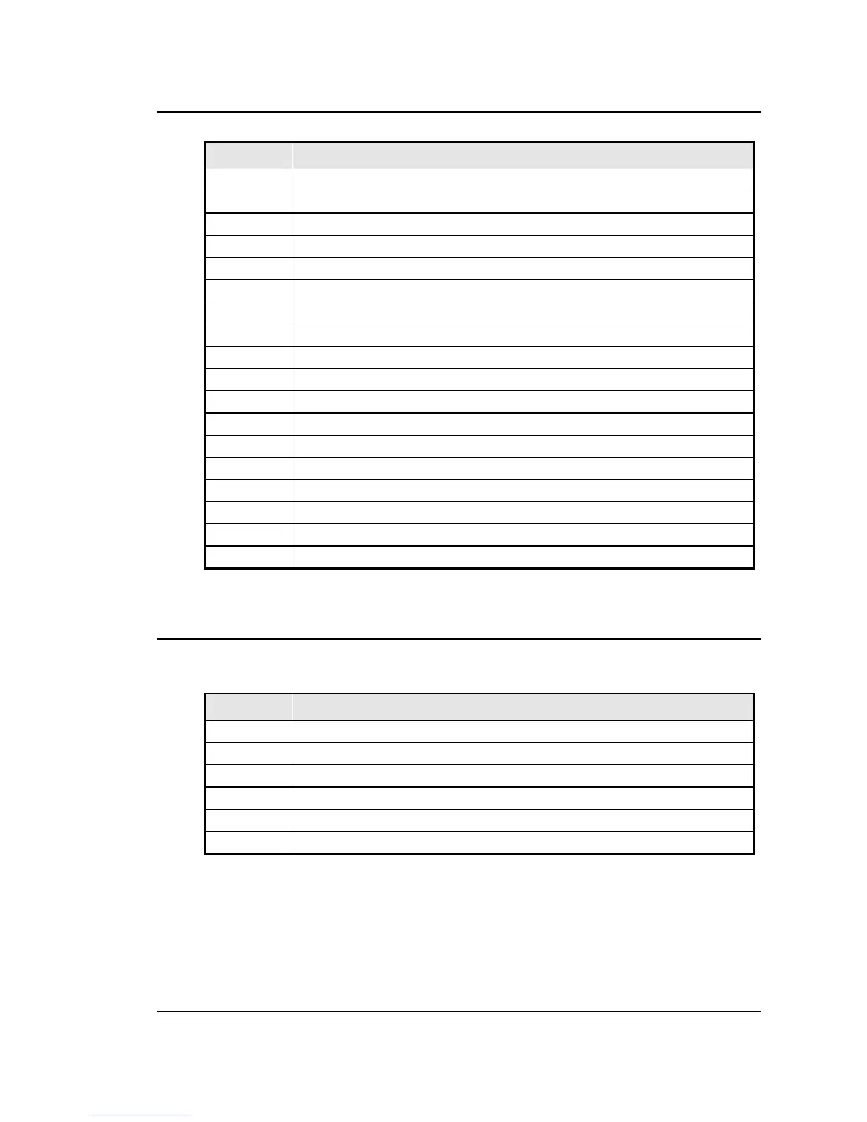
P8 / P9 Description
20 300 VRNG: 300 V AC Range Select
21 COM: Common. Signal return.
22 /REM OFF: Remote Off Control not
23 COM: Common. Signal return
24 FLK/BYP: Flicker / Bypass OMNI control
25 /OVL: Overload not
26 CLA: Current Limit A. Programmed current limit reference for phase A
27 CLC: Current Limit C. Programmed current limit reference for phase C
28 CSB: Current Sum Phase B.
29 N/C
30 FLT B: Amplifier Fault Phase B
31 N/C
32 DC: DC mode control
33 INP OFF: Input power control
34 A ERR HI: Error Signal Phase A, high
35 N/C
36 B ERR LO: Error Signal Phase B, low
37 C ERR HI: Error Signal Phase C, high
Table 3-4: System Interface Connectors
3.6.2 Analog Input Connector
Input screw-terminal strip. Functions are called out on rear panel decal. Table shows
connections from left to right when standing at the rear of the RS cabinet.
Pin Description
1 RPV HI. INPUT: Analog input for External Modulation
2 RPV Lo. INPUT: return.
3 EXT SYNC HI INPUT: Analog input for external sync mode.
4 EXT SYNC Lo INPUT: return.
5 RI: INPUT: Remote Inhibit. (See paragraph 3.11.)
6 RI: INPUT: return.
Table 3-5: Analog Interface Connector

 Loading...


