User Manual AMETEK Programmable Power
RS Series 43
3.5.4 RS180 Clock and Lock Output Wiring Diagram
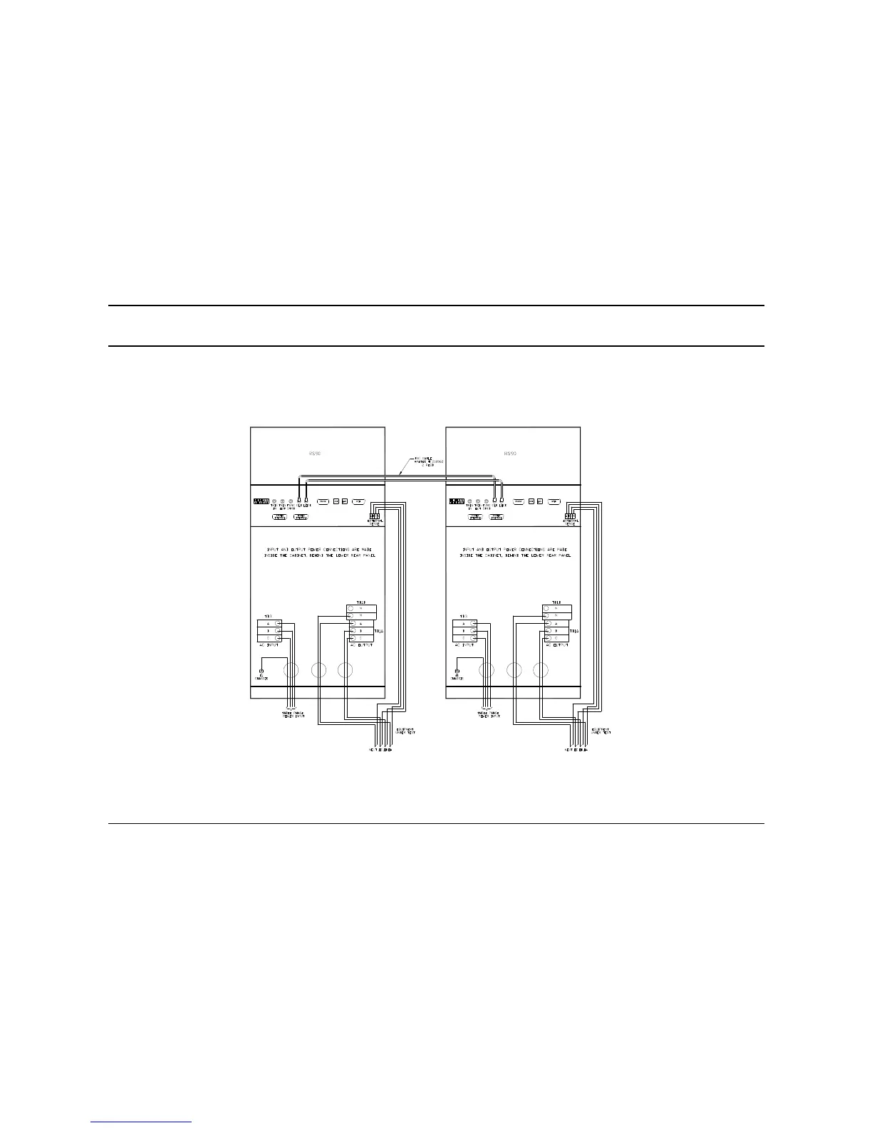
Figure 3-9 shows the required output connections for a RS90 Clock and Lock six phase output configuration (rear view). Always
disconnect all input power from the RS90 before removing the rear panel cover that provides access to the input and output terminal
connections. Clock and Lock systems can NOT be paralleled like a RS180 parallel system. Instead, they provide dual phase
synchronized 3 phase power sources with the auxiliary unit frequency and phase locked to the master power source.
Figure 3-9: Two RS90's in Clock and Lock mode Output Wiring (Rear view)

 Loading...


