User Manual AMETEK Programmable Power
RS Series 42
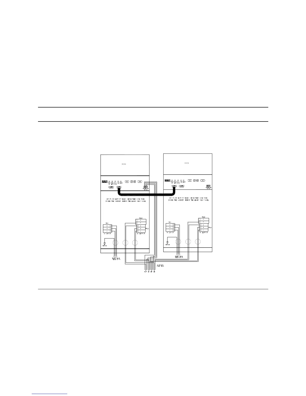
3.5.3 RS180 Parallel Output Wiring Diagram
Figure 3-8 shows the required output connections for a RS180 dual chassis parallel mode output configuration (rear view). Always
disconnect all input power from the RS90 before removing the rear panel cover that provides access to the input and output terminal
connections. RS180 systems are shipped with external output terminal blocks that enable the output wiring from two chassis to be
combined, providing a single point of connection to the EUT. These blocks must be installed in a suitable safety enclosure. It is important
to match the length of the output wiring to the common output terminal block to ensure current sharing between the two RS90 power
supplies. Additional RS90’s can be paralleled in the same way to create higher power configurations.
Figure 3-8: RS180 or RS180-MB Output Wiring (Rear view)
 Loading...


