Section 8 Status Structure
8-16
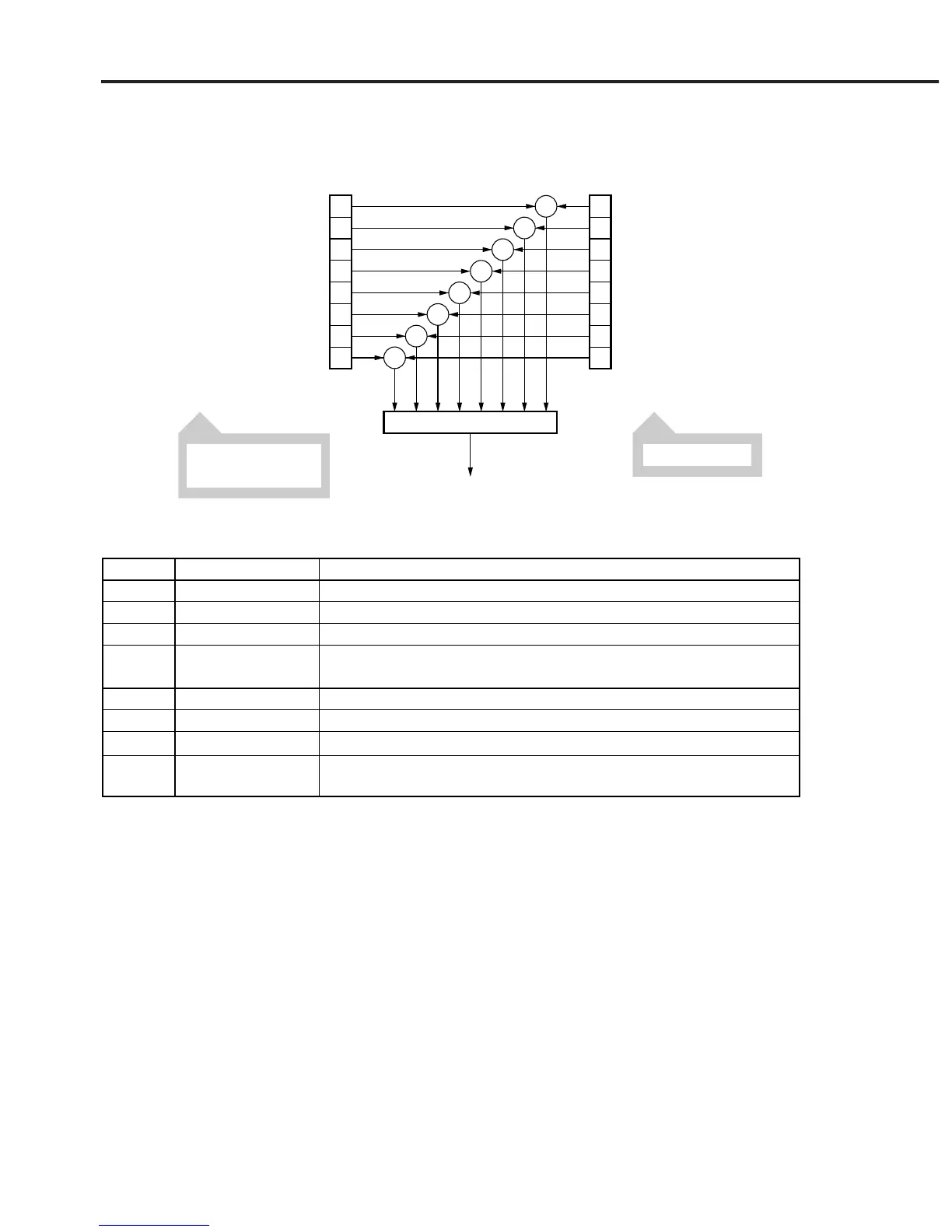
8.5.1 Definition of END event status register bits
This section explains END event status register model operation and names and
meanings of events.
7
6
5
4
3
2
1
0
7
6
5
4
3
2
1
0
&
&
&
&
&
&
&
&
Logical OR
ESB summary message bit
(to Status Byte register bit 2)
Not used
Not used
Not used
Execution complete
Execution complete
Transfer end
Sweep stop
Measurement end
END Event Status RegisterEND Event Status Enable Register
Read by ESR2?
Set with ESE2<NRf>.
Read with ESE2?.
disabled=0, enabled=128 (2
7
)
disabled=0, enabled=64 (2
6
)
disabled=0, enabled=32 (2
5
)
disabled=0, enabled=16 (2
4
)
disabled=0, enabled=8 (2
3
)
disabled=0, enabled=4 (2
2
)
disabled=0, enabled=2 (2
1
)
disabled=0, enabled=1 (2
0
)
Discription
Completion of ∗RST, wavelength calibration, automatic axis alignment, or res-
olution calibration
Completion of power monitor 1-point measurement or sweep averaging
Completion of transfer to FD or printer output
Single sweep stop
Completion of automatic measurement, analysis, peak/dip search, or applica-
tion measurement
Event name
Not used
Not used
Not used
Execution complete
Execution complete
Transfer end
Sweep stop
Measurement end
Bit
7
6
5
4
3
2
1
0