Section 6 Talker Output Format
6-4
6.2 Response Message Functional Elements
Response messages output from a talker are terminated with an NL^END signal, allowing the controller to accept
them. Functional elements of these response messages are explained here.
Rules for syntactical chart notation are the same as those for program messages, so see section 5. Functional and
coding elements which are the same as those of program messages are not explained in this section, so see section 5
for them.
6.2.1 <TERMINATED RESPONSE MESSAGE>
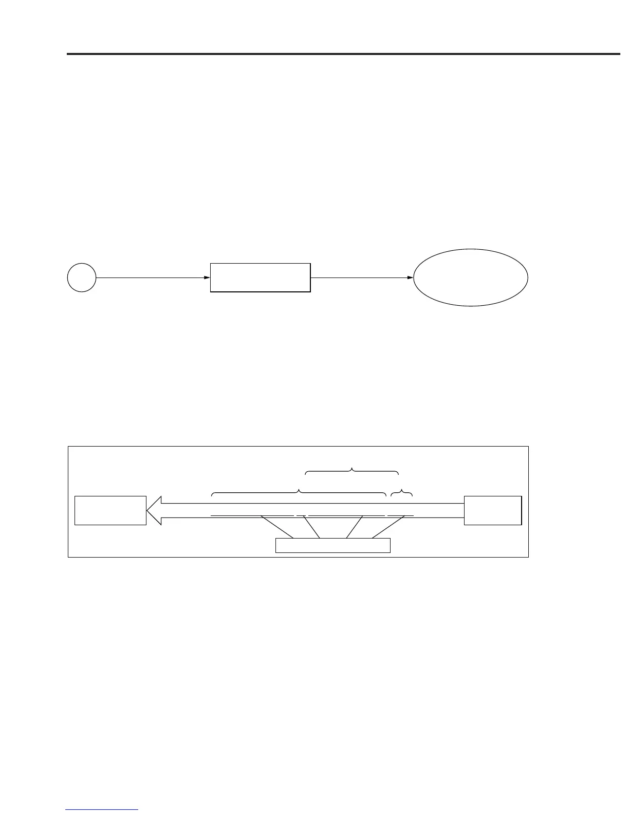
<TERMINATED RESPONSE MESSAGE> is defined as follows:
<RESPONSE MESSAGE>
Refer to 6.2.3
<RESPONSE
MESSAGE TERMINATOR>
Refer to 6.2.2
<TERMINATED RESPONSE MESSAGE> is a data message having all the necessary functional elements to be
sent from a talker to a device.
To complete transfer of <RESPONSE MESSAGE>, <RESPONSE MESSAGE TERMINATOR> is added at the
end of <RESPONSE MESSAGE>.
<Example> <TERMINATED RESPONSE MESSAGE> in which two message units are connected
Talker
(device)
Listener
(controller)
CNF 123ØØØØØØ ; SPF 1ØØØØØØ <NL>
<RESPONSE MESSAGE> <RESPONSE MESSAGE TERMINATOR>
Functional element
<TERMINATED RESPONSE MESSAGE>
Address 3