4-3
Initial Setting
4
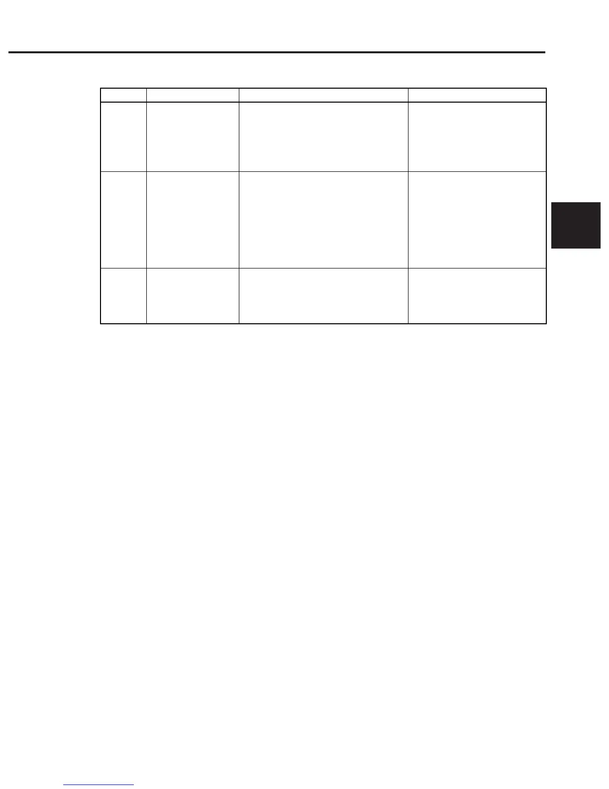
The following table provides a summary of the above explanation.
Overview
Combination and priority of levels
Interface functions of all devices connect-
ed to the bus are initialized by an IFC
message from a controller.
Message exchange is initialized and the
function of reporting completion of opera-
tion to the controller is disabled. This ini-
tialization can be ferformed either for all
devices on the GPIB using GPIB bus com-
mand DCL, or only for the specified
devices using a GPIB bus command SDC.
Only the specified devices on the GPIB
are initialized to the known states with an
∗RST command irrespective of the past
use state.
Initialization type
Bus initialization
Message exchange
initialization
Device initialization
Level
1
2
3
This level may be combined with
other levels. However, initializa-
tion at level 1 must be performed
before initialization at other lev-
els.
This level may be combined
withother levels. However, ini-
tialization at level 2 must be per-
formed before initialization at
level 3.
This level may be combined with
other levels. However, initializa-
tion at level 3 must be performed
after initialization at levels 1 and 3.
When controlled from a controller via the RS-232C interface port, the MS9710C
can use the “device initialization” function (level 3). However, it cannot use “bus
initialization” (level 1) and “message exchange initialization” (level 2) functions.
When controlled from a controller via a GPIB interface bus, the MS9710C can
use all the above initialization functions (levels 1 to 3).
Let’s take a look at the commands for performing initialization at levels 1 to 3 and
the items to be initialized as well as the known states set at power-on.