6-18 Replacing VNA PCB Assembly Assembly Removal and Replacement, MS202xC
6-32 PN: 10580-00307 Rev. D MS20xxC MM
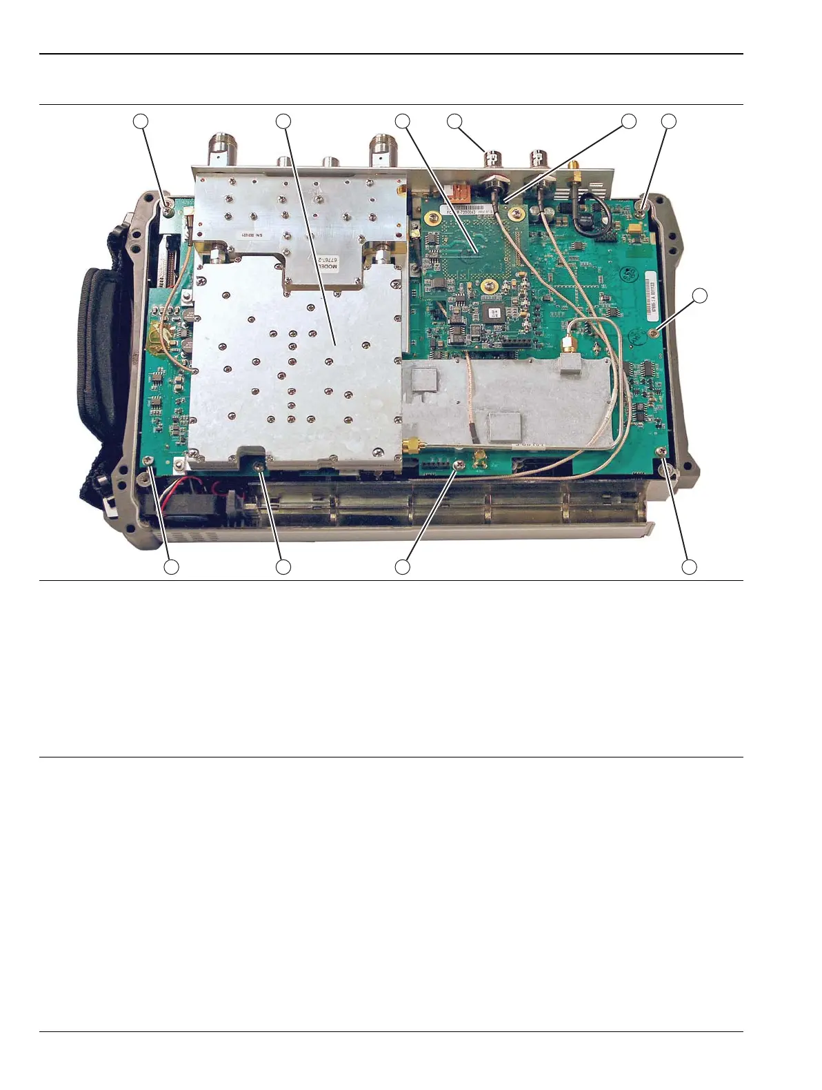
1. VNA PCB Assembly and related RF Shields with eight (8) total mounting screws
2. Location of Power Monitor Assembly PCB Option 5 with three (3) Phillips-head mounting screws
3. Remove the castellated nut and loosen the Ext Trig Input BNC Connector before removing Power Monitor PCB
4. The first VNA PCB Assembly Phillips-head mounting screw under Power Monitor PCB
5. 6, 7, 8, 9, 10, and 11. Additional Phillips-head mounting screws (7 total) holding VNA PCB Assembly in place
Note that cables in this figure may not match newer VNA Master MS202xC instruments. Refer to Figure 6-15
on page 6-33.
Figure 6-14. VNA PCB Assembly Screw Locations
 Loading...


