Assembly Removal and Replacement, MS202xC 6-18 Replacing VNA PCB Assembly
MS20xxC MM PN: 10580-00307 Rev. D 6-33
Removing the VNA PCB Assembly:
7. Using a Phillips-head screwdriver, remove the eight (8) screws holding the VNA PCB Assembly in place.
8. Gently lift the top connector plate clear of the case front and raise the VNA PCB Assembly just enough to
slide it toward the top of the case in order to expose the connectors along the lower edge of the Main PCB
Assembly (Mother Board).
Note
These eight screws attach the VNA PCB Assembly to 8 standoffs, which secure the Main PCB
Assembly (MB) to the front case.
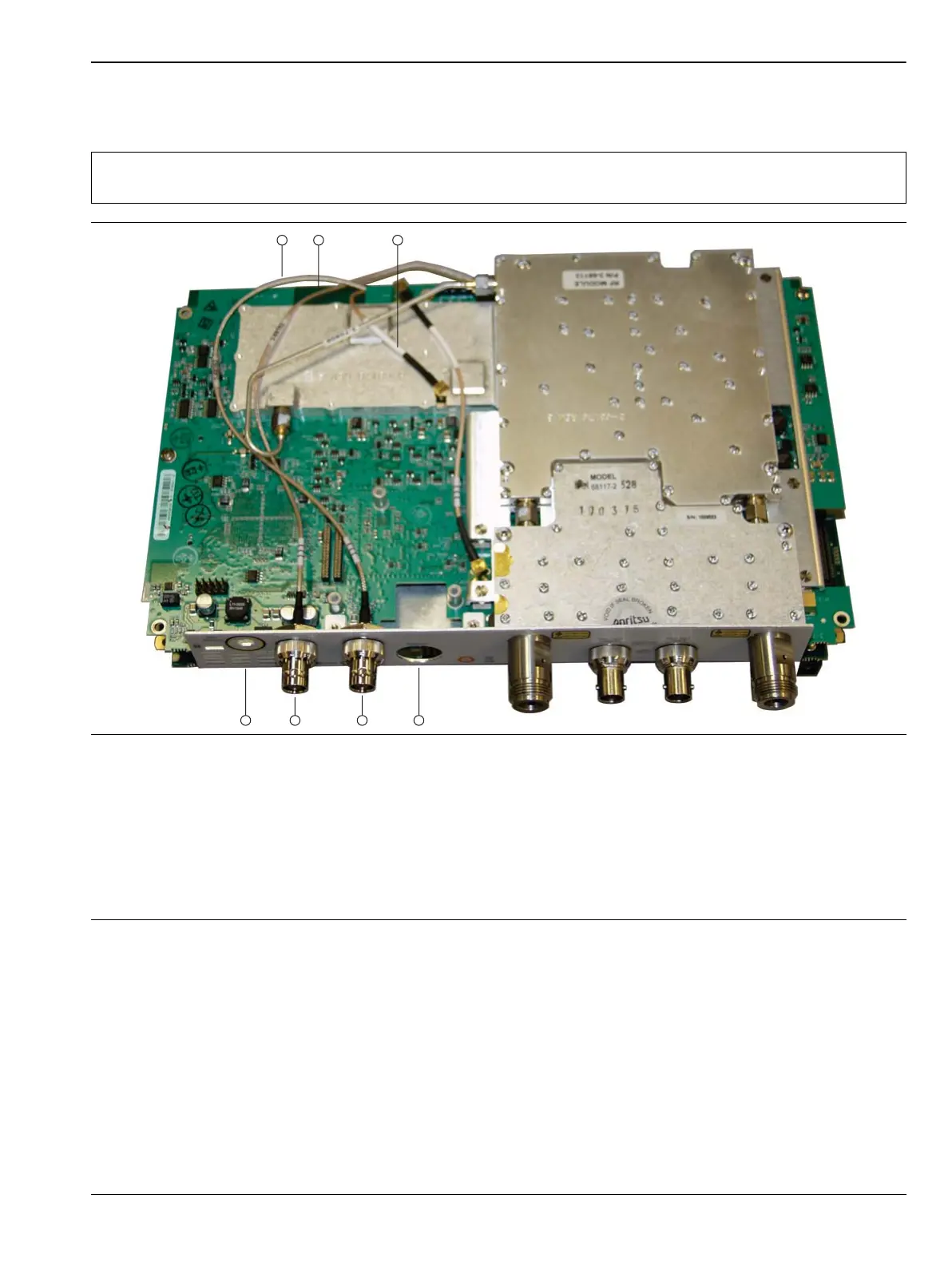
1. Cable, Ext Trig Input, to MB J3202
2. Cable, Ext Ref Input, to MB J2200
3. Cable, VNA Reference, 26 MHz, to MB J2201
4. Location of Power Monitor Connector (Option 5) or hole plug (Power Monitor option not installed)
5. External Trigger Input Connector
6. External Reference Input Connector
7. Location of GPS Antenna Connector (Option 31) or hole plug
Figure 6-15. Cables Connecting Main PCB (Mother Board) and VNA PCB (MS2028C shown)
 Loading...


