6-18 Replacing VNA PCB Assembly Assembly Removal and Replacement, MS202xC
6-34 PN: 10580-00307 Rev. D MS20xxC MM
9. Use needle-nose pliers to remove the following 3 cable connections from the Main PCB Assembly, leaving
the cables attached to the VNA Assembly (refer to Figure 6-15 and Figure 6-16):
a. Ext Ref Input cable (from connector panel) at J2200, 100 MHz, MMCX connector (Item 10 in
Figure 6-16)
b. VNA Module cable (from connector in top shield) at J2201, 26 MHz Out, MCX connector (Item 9 in
Figure 6-16)
c. Ext Trig Input cable (from connector panel) at J3202, Trig In, MMCX connector (Item 8 in
Figure 6-16)
10. Remove the VNA PCB Assembly with cables attached, and set it aside.
Preparing the Replacement VNA PCB Assembly:
Exchange cables from the removed VNA PCB Assembly to the new VNA PCB Assembly. Note that the
castellated BNC dress nut torque specification is 7.5 lbf·in (0.85 N·m).
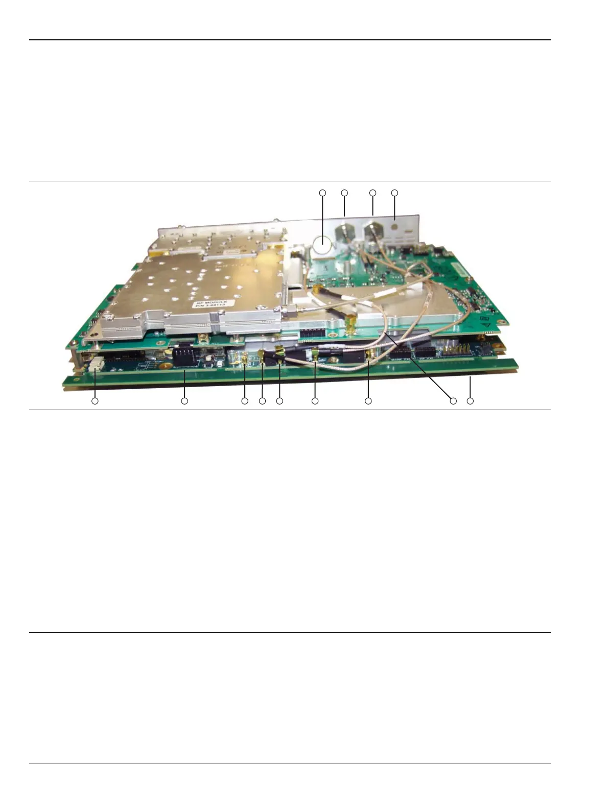
1. Connector Panel opening for Power Monitor (Option 5) RF Detector Interface
2. External Trigger Input connector
3. External Reference Input connector
4. Capped opening for GPS (Option 31) Antenna Connector
5. General location of connector J4202 on Mother Board (for LCD signal cable)
6. Cable for VNA reference, 26 MHz Out (from Mother Board connector J2201)
7. MB J3203, MMCX connector for 140 MHz IF (not used in MS202xC models)
8. MB J3202, MMCX connector for External Trigger (for Item 3)
9. MB J2201, MCX connector for 26 MHz Out to VNA module (cable is Item 6)
10.MB J2200, MMCX connector for External Reference Input (for Item 3)
11.MB J2202, MMCX connector for 100 MHz Out (not used in MS202xC models)
12.MB J1003, Battery connector
13.MB J1002, Fan connector
Figure 6-16. Cables Connecting Main PCB (Mother Board) and VNA PCB (MS2028C shown)
 Loading...


