6-21 Removing MS202xC Main PCB Assembly Assembly Removal and Replacement, MS202xC
6-46 PN: 10580-00307 Rev. D MS20xxC MM
13. Near the handle side of the case, disconnect the cable from the Rotary Encoder PCB. The Rotary Encoder
stays mounted in the Case Front Assembly.
14. Near the bottom of the case, disconnect the Battery Cable and the Fan Cable from the Main PCB and fold
them over the case edge clear of the PCB.
15. Holding the standoff (item 2 in Figure 6-17), apply a slight pressure to the Mother Board toward the top
of the case by pressing on a shield. The connectors (External Power Input, LAN, USB, and Headset Jack)
protrude into the Case Front. Lift on the standoff to pivot the Main PCB against the top of the case until
the connector to the Main Keypad Assembly is disconnected.
16. Carefully lift the entire Main PCB from the case by drawing the Lan and USB connectors away from the
case top. Then set the Main PCB aside.
17. At this point, proceed with any of the following replacement procedures:
• Section 6-22 “Replacing MS202xC Main PCB Assembly” on page 6-47
• Section 6-23 “Replacing LCD Display – 3-15-154” on page 6-50
• Section 6-24 “Replacing Clear Plastic LCD Protector – 3-61368” on page 6-51
18. After the required replacement procedures are complete, reassemble the instrument using the procedure
in Section 6-25 “Installing Main PCB and Reassembling Instrument” on page 6-52.
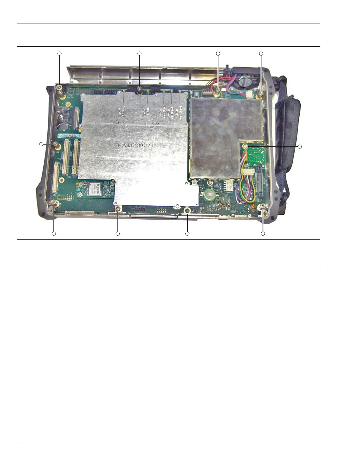
8 Hexagonal Standoffs, items: 1, 2, 3, 4, 6, 8, 9, 10. Remove items 1, 3, 4, 6, 8, 9, and 10.
Do not remove standoff, item 2.
2 Pan Head Screws, items: 5 and 7, remove both
Figure 6-17. Screws and Standoffs that Secure the Mother Board to the Case Front
 Loading...


