Assembly Removal and Replacement, MS203xC 7-16 Opening the Instrument Case
MS20xxC MM PN: 10580-00307 Rev. D 7-27
5. Carefully lift up on the sides of the case, as shown, and begin to separate the two halves. The top
connector panel slides in grooves of the case back until the case halves are far enough apart to separate
them.
6. As shown in Figure 7-5 on page 7-7 and Figure 7-7 on page 7-9, several cables connect between the front
case and the back case.
7. Using care to avoid stress on the cables, pivot the case back as if it were hinged to the case front along the
edge with the handle (carrying strap), and lay the case back (with SPA PCB face up) next to the case
front.
1. Remove Battery Access Door and Battery.
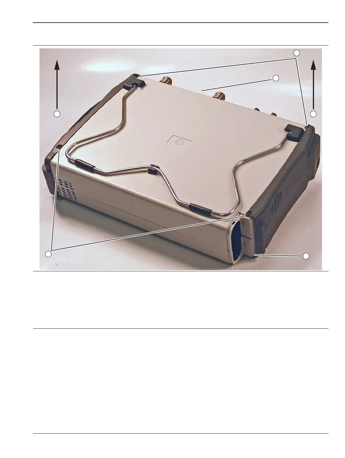
2. Orient case with connector panel as shown.
3. Remove two (2) Phillips-head screws at top.
4. Remove two (2) Phillips-head screws at bottom.
5. At both ends of the Case Rear, lift up both ends evenly.
The top connector panel stays with the Case Front Assembly.
Figure 7-13. Opening the Case
 Loading...


