7-16 Opening the Instrument Case Assembly Removal and Replacement, MS203xC
7-28 PN: 10580-00307 Rev. D MS20xxC MM
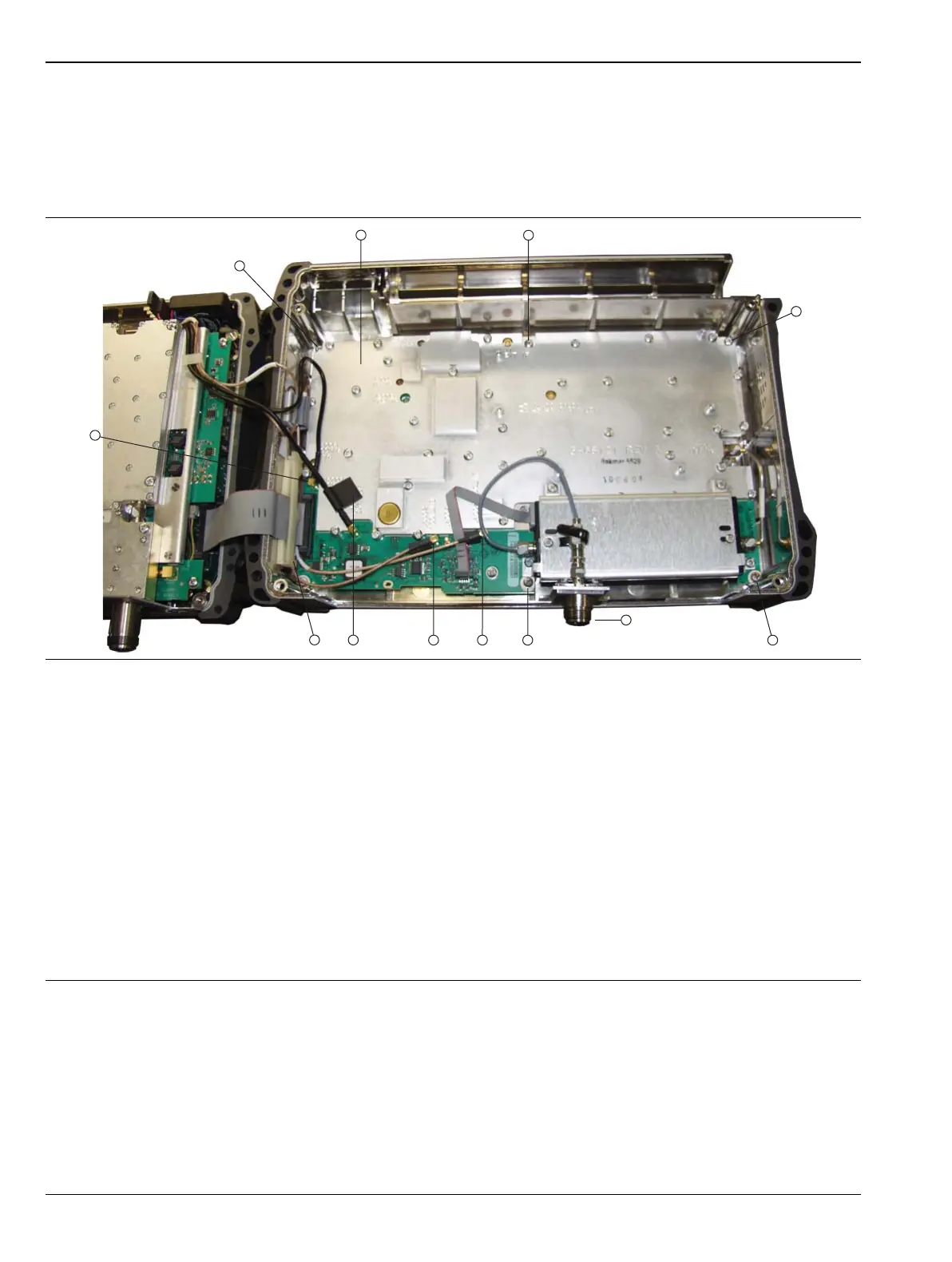
8. Disconnect the Spectrum Analyzer cable assembly (ribbon cable, item 14 in Figure 7-5, and item 14 in
Figure 7-7) from connector J5001 of the SPA board in the back case. For a visual reference with all cables
connected, refer to Figure 7-14 on page 7-28.
a. Snap open the cable clamp first (shown open in Figure 7-16 on page 7-33).
b. Spread the latch arms on the connector block, then pull out the cable connection.
9. Snap open the other cable clamp in the back case, and then use needle-nose pliers to disconnect the four
single cables from MMCX connectors J6000, J6001, J6002, and J4004.
a. J6000 (item 9 in Figure 7-14) is for the External Reference cable from the Ext. Ref. connector on
the top connector panel (attached to the VNA Assembly).
b. J6001 (item 11 in Figure 7-14) is for the 10 MHz Ref Out connector on the top connector panel
(attached to the VNA Assembly).
1. PCB
2. Screw (1 of 6 holding PCB to case back)
3. Screw (1 of 6 holding PCB to case back)
4. Screw (1 of 6 holding PCB to case back)
5. SPA RF In Connector (protrudes through connector panel of VAN Assembly when instrument is assembled)
6. Screw (1 of 6 holding PCB to case back)
7. MMCX Connector J4004, 140 MHz IF
8. Connector J6002, 100 MHz to MB (Mother Board)
9. Connector J6000, External Reference In
10.Screw (1 of 6 holding PCB to case back)
11.Connector J6001, 10 MHz Reference Out, located adjacent to J5006 (for ribbon cable)
12.Screw (1 of 6 holding PCB to case back)
Figure 7-14. SPA PCB in Case Back – Cables Connected
 Loading...


