7-17 Replacing SPA Module Assembly Assembly Removal and Replacement, MS203xC
7-36 PN: 10580-00307 Rev. D MS20xxC MM
Replacing Case Rear Assembly:
16. Replace the Case Bottom Assembly. Ensure that the SPA connector plate is properly engaged within the
top connector panel. Ensure that the top connector panel is correctly centered in its mounting groove and
that all cables are clear.
a. Insert and tighten the four SPA connector plate mounting screws. Torque these screws to
4.0 lbf·in (0.45 N·m).
b. Insert and tighten the four case mounting screws. Torque the screws to 7.5 lbf·in (0.85 N·m).
Installing Battery:
Refer to Section 5-4 “Battery Pack Removal and Replacement” on page 5-3.
17. Install the Battery.
18. Install the Battery Door.
Restarting the Instrument:
19. Restart the instrument.
20. Perform a function check to verify all repairs and part replacements.
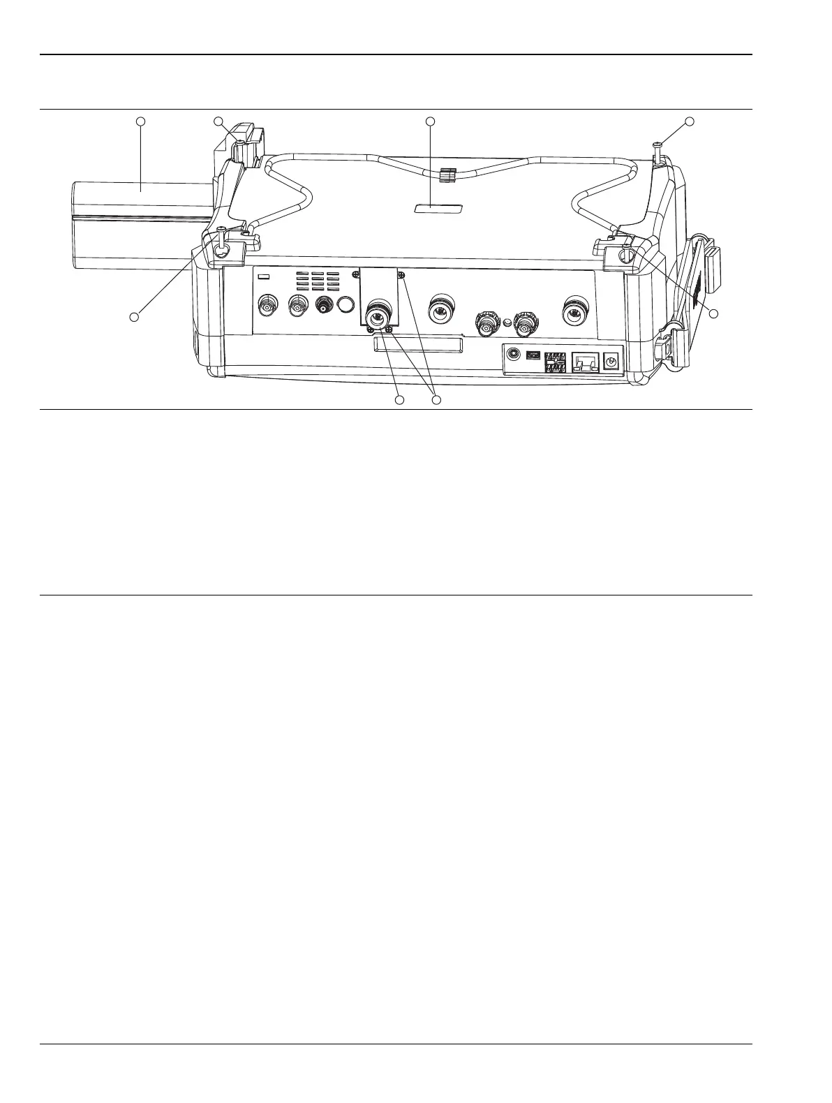
1. Battery
2. Case Back screw (1 of 4)
3. Recess for serial number label (serial number of SPA PCB)
4. Case Back screw (1 of 4)
5. Case Back screw (1 of 4)
6. Screws (4) to hold SPA RF In connector mounting plate to top connector panel
7. SPA RF In port (supplied with SPA PCB)
8. Case Back screw (1 of 4)
Figure 7-17. Case for MS203xC

 Loading...


