4-2 Power Monitor (Option 5) Verification Options Performance Verification
4-2 PN: 10580-00307 Rev. D MS20xxC MM
9. On the MG3692X, press the Level key and then use the rotary knob to adjust the power level so that the
power meter reads –40 dBm.
10. Verify that the VNA Master reading is within the specification shown in Table 4-1 on page 4-3. Record
the result to Table A-2, “Power Monitor Measurement Accuracy” on page A-2 for MS2026C, to Table A-4,
“Power Monitor Measurement Accuracy” on page A-3 for MS2027C or to Table A-6, “Power Monitor
Measurement Accuracy” on page A-4 for MS2028C.
f
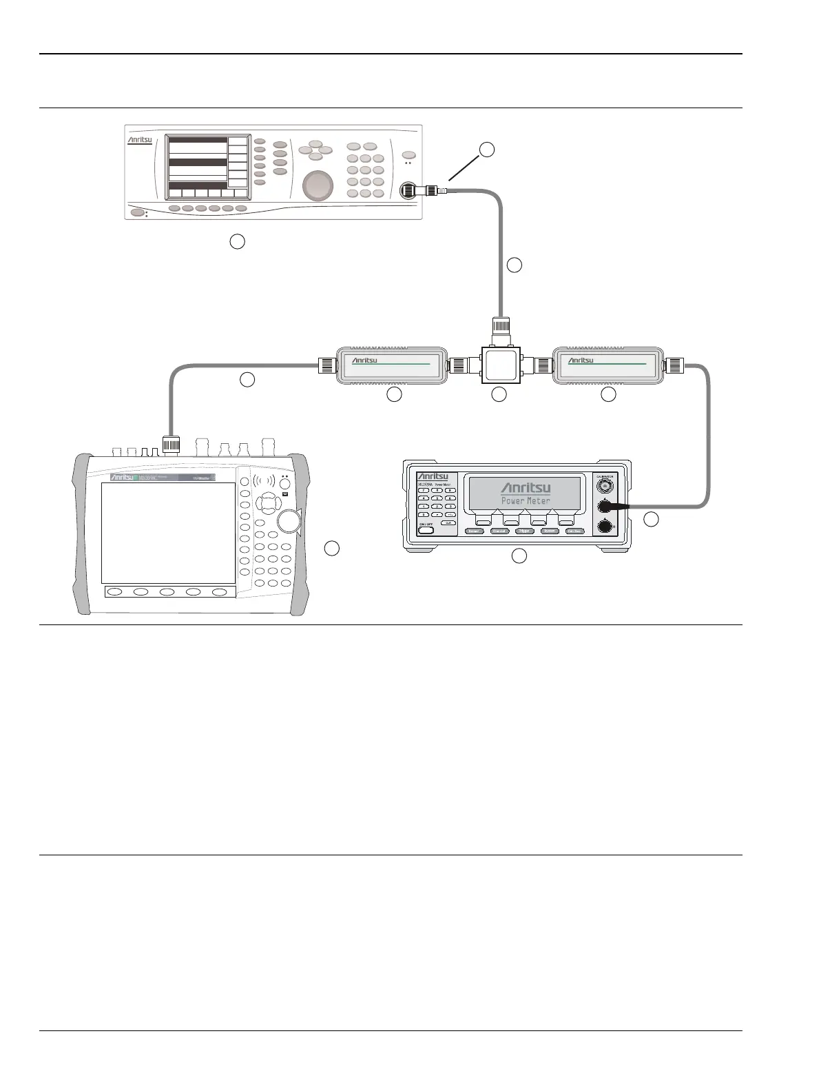
1. Anritsu MS2026C or MS2028C VNA Master
2. Detector Cable
3. Anritsu RF Detector, PN 560-7N50B
4. Power Splitter, Aeroflex/Weinschel Model 1870A
5. RF Coaxial Cable
6. Anritsu Adapter, PN 34RKNF50
7. Anritsu MS3692X Synthesized Signal Generator with Option A2 and Option 4 (or Option 5)
8. Anritsu Power Sensor, PN MA2442D
9. Power Sensor Cable
10.Anritsu ML243XA Power Meter
Figure 4-1. Power Monitor Verification Test Setup

 Loading...


