i2000SR interface module Service Manual
Page 84 of 212 625798100.APS.5.doc
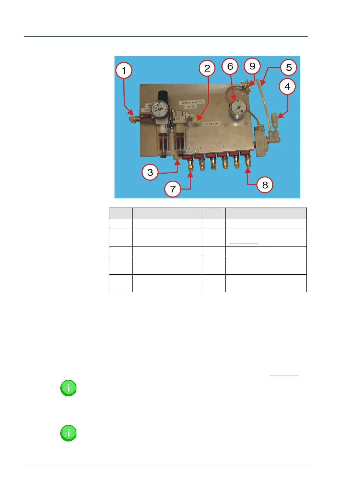
Figure 69 – IOM Pneumatic Panel (new style)
Item Function Item Function
1 Air supply line 6 IOM Panel Output Gauge
2 Output to tank 7 i2000SR IM [A] (See
Figure 69
)
3 From tank 8 Storage Retrieval Module
4 To IOM Robot and
Workcell
9 Control Interface
5 To IOM Panel Output
Gauge
• At the storage module pneumatic panel, trace the input
line to its first connection.
• Using the 6 mm diameter tubing SMC TUPU0604 (P/N
PNT0003) supplied; make a connection between Storage IOM air
input and the new pneumatic panel storage connection [8].
• Using the 6 mm diameter tubing SMC TUPU0604 (P/N
PNT0003) supplied; make a connection from the IOM pneumatic
panel [7] to the i2000SR IM pneumatic panel [A] (See
Figure 69
).
NOTE:
The Festo Sensor is no longer being used to monitor the
movement of the Z-Axis. The tubing will be disconnected at
the Z-axis regulator.
NOTE:
If this procedure is being performed before the installation