Service Manual i2000SR interface module
625798100.APS.5.doc Page 91 of 212
STEPS REFERENCES
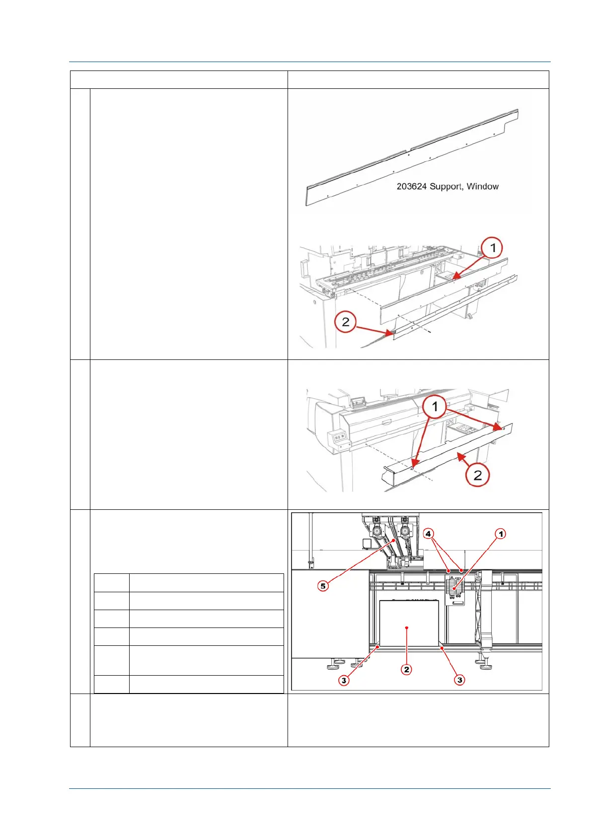
9 At the front of the i2000SR IM,
remove the six (6) 100474-001
screws used to mount the 203624
Window Support [1] and 203718
Bracket Lower Closeout.
10 Remove the two (2) screws used to
secure the 203717 Lower Closeout to
the Window Support.
11 Refer to the pneumatic working
drawing and electrical wiring diagram
to remove pneumatic and electrical
connections. Then remove Pneumatic
panel and electrical box.
No. Description
1 Pneumatic panel
2 Electrical box
3 Electrical box fasten points
4 Pneumatic panel fasten
bolts
5 i2000SR IM body
12 At each of the four (4) i2000SR feet,
mark the position on the floor and
measure the distance between the
bottom of the frame and the floor.