i2000SR interface module Service Manual
Page 92 of 212 625798100.APS.5.doc
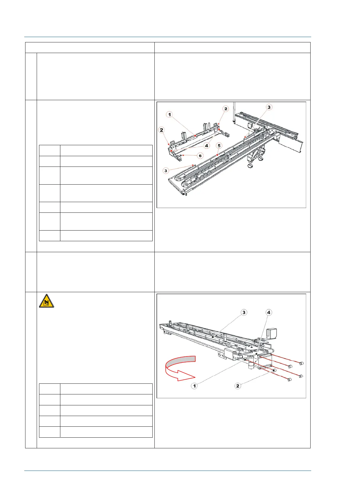
STEPS REFERENCES
13 Adjust the feet as required to lower
the i2000SR and move the module
away from the IM.
As the i2000SR IM is no longer being
supported, a second person is
required to hold and support the IM.
14 Loosen the i2000SR bracket
attachment screw to release the
i2000SR IM from i2000SR. At the
underside of the IM, loosen the two-
knurled knobs to lower the support
bracket.
No. Description
1 i2000SR insert spur rail
2 i2000SR insert spur rail cut-
off
3 i2000SR IM assembly cut-
out extreme limits
4 i2000SR slider spur supports
5 i2000SR IM assembly cut-
out
6 i2000SR bracket attachment
15 Disconnect all electric and pneumatic
connections between i2000SR,
i2000SR IM and TMA.
Remove the pneumatic multi
connector bracket.
16
CAUTION: Lift Hazard
Two people are required to remove
the i2000SR IM from the workcell, one
person to hold i2000SR IM module
and the other to loosen the bolts. The
i2000SR IM gross mass is 18 kg
(~40 lbs).
Remove the five screws securing the
i2000SR IM to the TMA assembly.
Remove i2000SR IM moving it in the
direction of the arrow shown below.
No. Description
1 Screw
2 Nut
3 i2000SR IM
4 Disk