Service Manual i2000SR interface module
625798100.APS.5.doc Page 93 of 212
STEPS REFERENCES
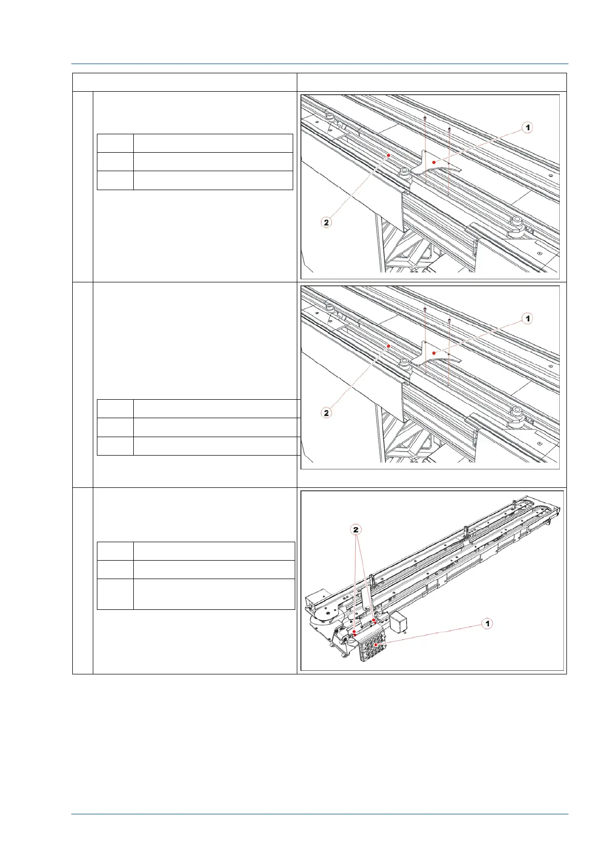
17 Loosen the two screws from TMA
assembly to remove the disk’s
metallic top protection [1].
No. Description
1 Disk upper protection
2 TMA assembly
18 Remove the new i2000SR IM group
from the shipping platform and
remove the packaging protection
covers.
Mount the disk’s metallic top
protection and fasten it on the TMA.
That protection’s inner profile will be
the alignment reference line for the
i2000SR IM.
No. Description
1 Disk upper protection
2 TMA assembly
19 To allow better access the to the
mounting screws, remove the
pneumatic multi connector bracket
by removing the two (2) M4 screws.
No. Description
1 Pneumatic multi connectors
2 Pneumatic multi connectors
fixing screws