i2000SR interface module Service Manual
Page 94 of 212 625798100.APS.5.doc
STEPS REFERENCES
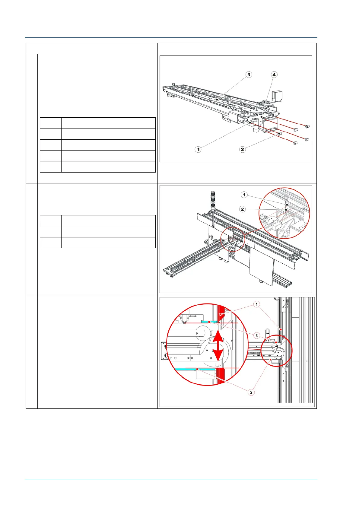
20 Locate on the i2000SR IM the five
plastic mounting bolts
NOTE:
As the i2000SR IM is mounted to the
TMA, use care to prevent damage to
the large Autotex disk.
Fasten each bolt to fix the i2000SR
IM.
No. Description
1 Screw
2 Nut
3 i2000SR IM
4 Autotex disk
.
21 Insert the five square nuts in the side
grooves of the TMA extruded profile:
three nuts in the top groove and two
in the bottom one.
No. Description
1 Top groove
2 Bottom groove
22 Locate the main track opening.
Position the IM track external profiles
[3] to align the inner surface [2] with
the main track separators [1].