Service Manual i2000SR interface module
625798100.APS.5.doc Page 95 of 212
STEPS REFERENCES
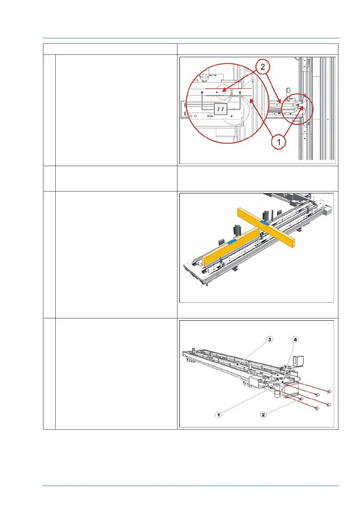
23 Note that the Disk upper protection
[1] is in alignment with the guide
between tracks 1 and 2 [2].
Use the Oversized Pallet tool (P/N
475.110.031) to verify that both input
and exit lanes are equal in width and
that the carrier template can move
freely.
24 Using the floor reference marks,
reposition the i2000SR and adjust
each foot to set the proper height
25 Place two TM Carrier Leveling Aids
(P/N 403.600.150 (202182)) in a belt
track.
Position the aids so that they will
span the length of the IM.
Place a bubble level between the two
aids and check that the length of the
IM is level.
Place one aid on belt 1 and the other
on belt 4.
Use the bubble level to check the
width of the IM.
NOTE:
TM Carrier Leveling Aid (P/N
403.600.150 (202182) is not shown in
figure.
26 If it is not possible to obtain a good
level, loosen the five (5) bolts used to
mount the IM and adjust the plane of
the i2000SR IM.