i2000SR interface module Service Manual
Page 96 of 212 625798100.APS.5.doc
STEPS REFERENCES
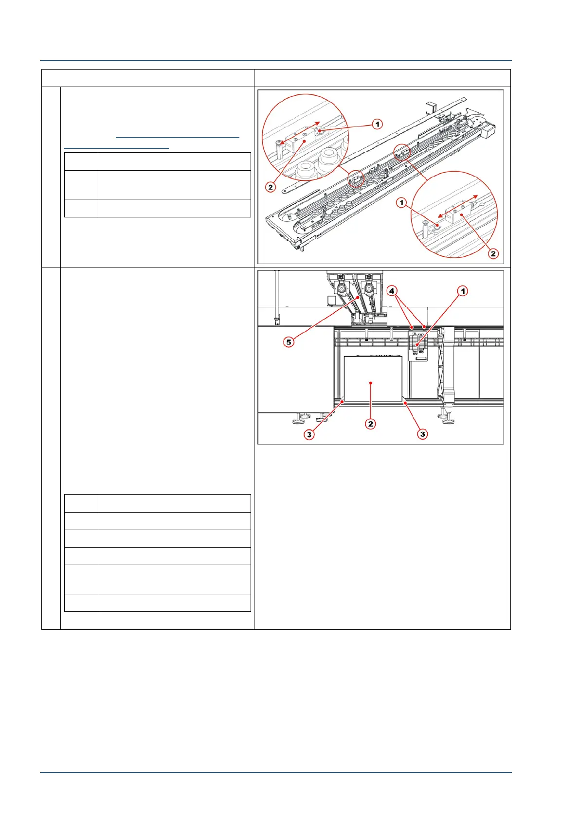
27 Verify that the two carriers at the
stop gate are under the vertical of
the i2000SR sample points.
If not, see
Alignment of routine and
STAT sampling gates
procedure.
No. Description
1 Screw to loosen for stop
gate fine positioning
2 Sample points stop gate
28 Install Pneumatic panel on the TMA.
The manufacturer has not defined the
exact position as to where to fasten
the Pneumatic panel on the TMA. The
FSE will have to look for a convenient
fixing point avoiding TMA feet
encumbrance.
Do not install the pneumatic panel at
the left of the IM or it will be
unreachable for maintenance
operations because it will be covered
by the i2000SR.
Refer to the pneumatic working
drawing to re-establish pneumatic
connections. Each pneumatic tube is
identified with two labels, one on
each tube extreme and has to be
connected to the corresponding
labeled devices.
No. Description
1 Pneumatic panel
2 Electrical box
3 Electrical box fasten points
4 Pneumatic panel fasten
bolts
5 i2000SR IM body