Service Manual i2000SR interface module
625798100.APS.5.doc Page 97 of 212
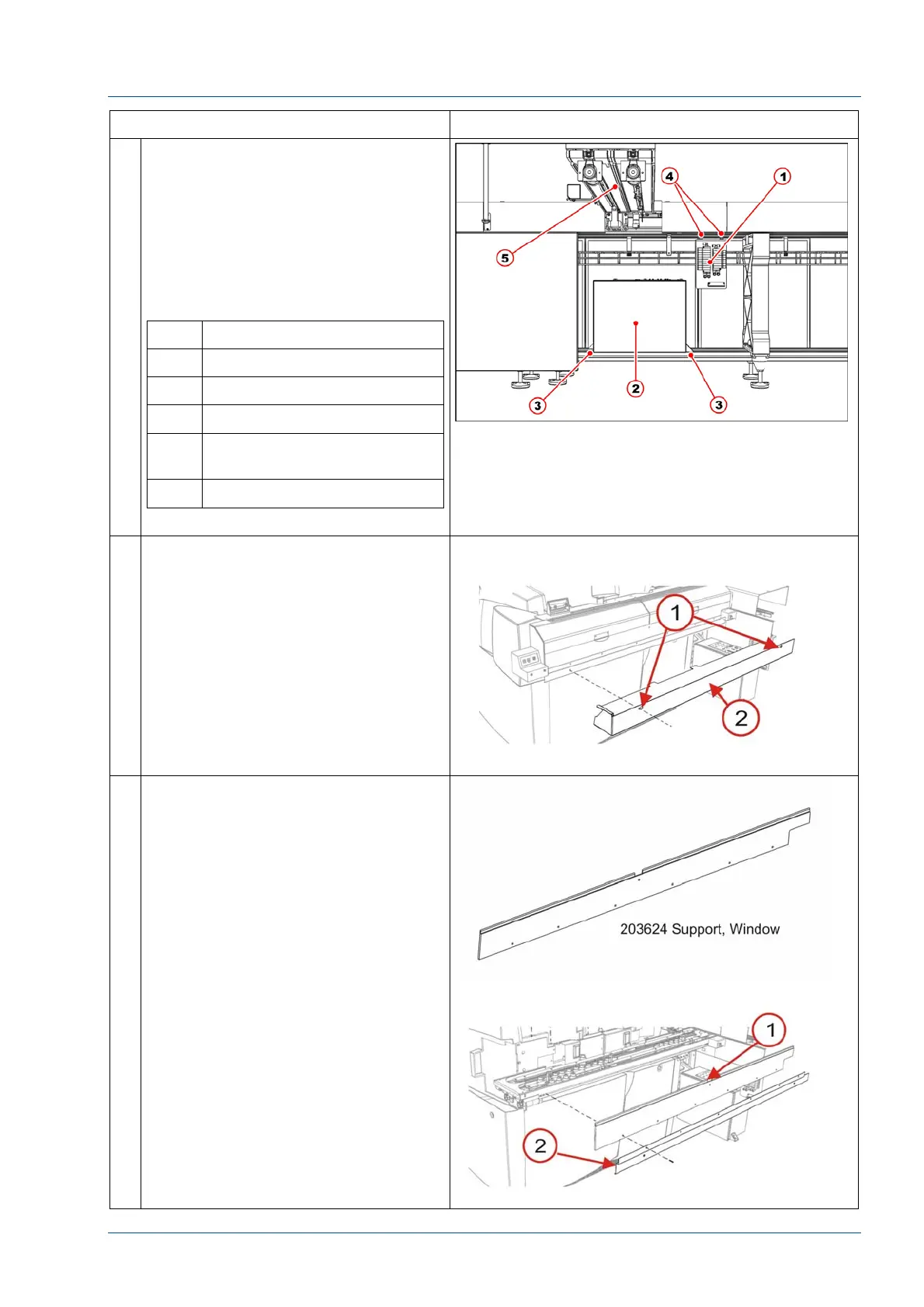
STEPS REFERENCES
29 Install the electrical box on the Track
Module Assembly (TMA).
Do not install the electrical box at the
left of the IM or it will be unreachable
for maintenance operations because
it will be covered by i2000SR.
Refer to the electrical working
drawing to re-establish electrical
connections.
No. Description
1 Pneumatic panel
2 Electrical box
3 Electrical box fasten points
4 Pneumatic panel fasten
bolts
5 i2000SR IM body
30 Using two (2) screws, secure the
203717 Lower Closeout to the
Window Support.
NOTE:
Use care to ensure that all cables and
tubing are not pinched, crimped or
damaged.
31 At the front of the i2000SR IM, install
the six (6) 100474-001 screws to
mount the 203624 Window Support
[1] and 203718 Bracket Lower
Closeout.