17-10
PPC Manual Revision 1
Chapter 17: Software Setting Flow and Navigation
a list of parameters to be switched to the next list. Clicking [BACK] causes a list of parameters
to be switched to the previous list.
Parameter setting sequence
First set parameters relating to the input/output of setup parameters (menus CTL, PV,
RSP, MPV_L1, MPV_L2, and OUT), then set the other setup parameters. After setting
most of the setup parameters, set the operation parameters.
Note
▪ Parameters to be displayed are the same as those in the “easy setting mode” of the
controller irrespective of the software parameter view level.
▪ If setup parameter(s) are set after setting the operation parameters, there may be cases in
which the operation parameters are initialized.
What are register symbols?
Register symbols are the symbols of registers containing data such as controller
parameter, operation status, alarm status, contact input, and error information in 16 bits
or 1 bit.
When performing communication, registers are used as D-registers or I-relays.
D-register symbols
For some register symbols, the loop number, terminal area number, and group
number are indicated by adding the underscore (_) to the end of a parameter symbol.
If both the loop number and group number are added to a parameter symbol, they are
added to it in the order of _loop number and _group number.
xxxx_Ln_Y
Ln: loop number (L1 or L2)
Y: group number (1 to 8 (20) or 1 to 16, R)
xxxx_En
En: terminal area number (E1 or E3)
Example:
SP_L1_3: This means Loop-1 group-3 target setpoint.
PYS_2: This means group-2 PYS.
DI1.D_E1: This means E1-terminal area DI1.D.
Menu symbols and parameter symbols different from those in the controller
For menu symbols and parameter symbols, the loop number and terminal area
number are indicated like register symbols. For example, the alarm function menu is
indicated as ALRM in the controller, while it is indicated as ALRM_L1 in the software.
For the notation, refer to “D-register symbols” above.
▪
Alarm function setting parameters
In the controller, the alarm type, stand-by action, energized/de-energized, and latch
settings are made using one parameter. However, they are set using one parameter
each in the software.
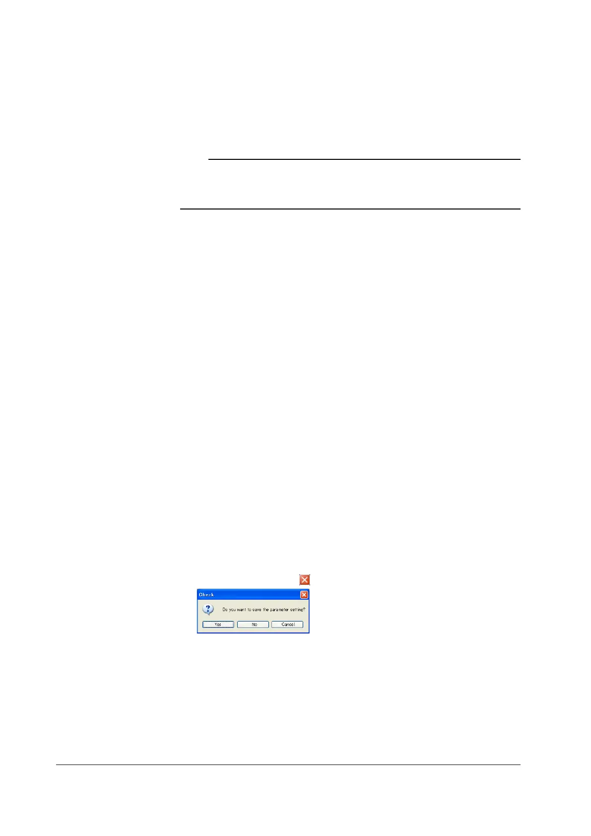
4.
This message dialog is also displayed if the NEXT button is clicked until the end.

 Loading...

