Installation
42 AVENTICS | Marex 3D | R417003094–BDL–001–AA
apply the shield to the cone within the cable gland of the
connected devices.
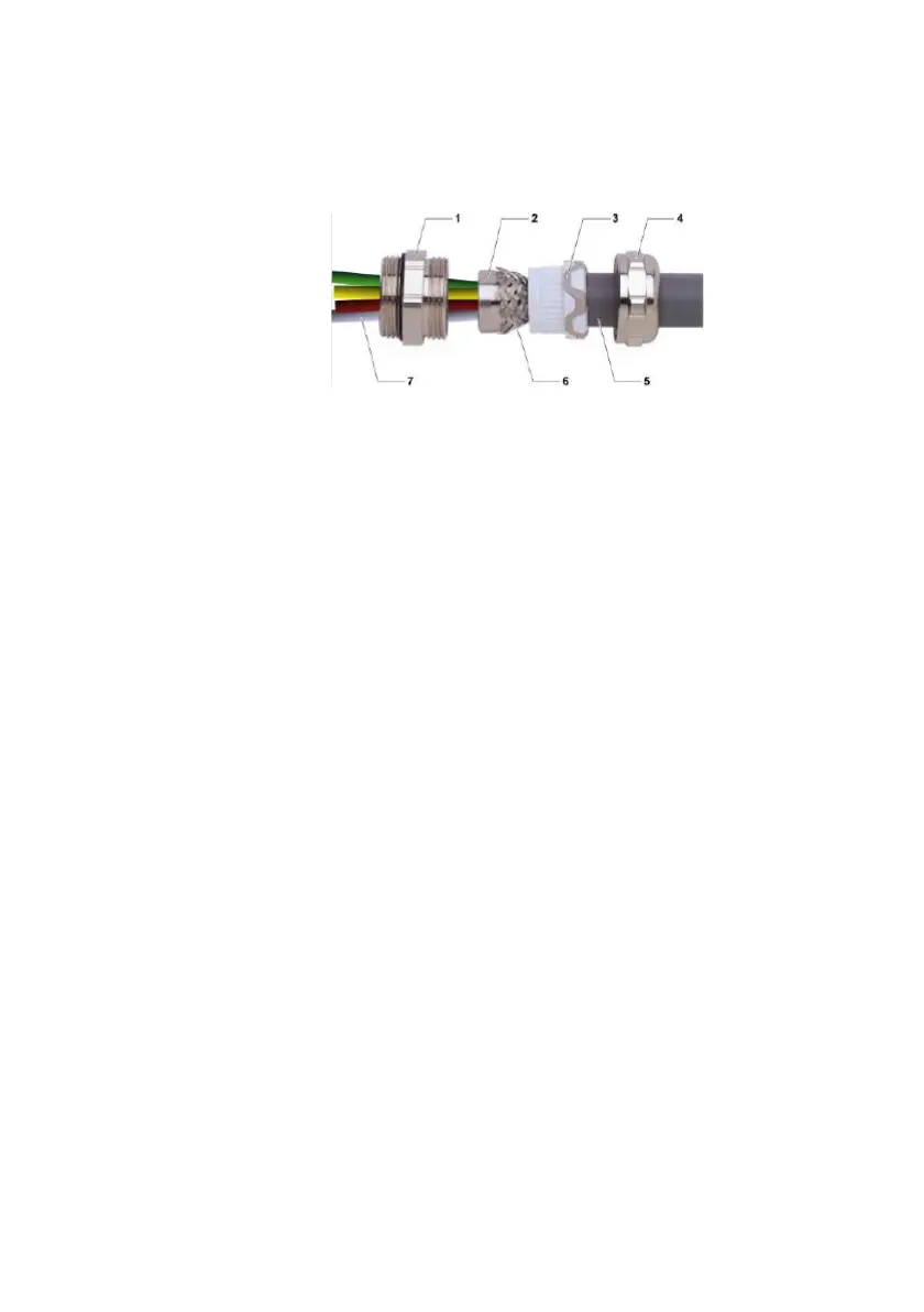
Fig. 14: Cable gland
Proceed as follows:
1. Strip off the insulation over a sufficient length that allows
you to connect the individual wires to the housing.
2. Allow approx. 1.5 cm of the braided shield (6) to project from
the insulating sheath.
3. Remove the cover from the opening in the housing where
you want to install the cable gland.
4. Insert the double nipple (1) and the cone (2) into the opening
of the housing from the outside. Make sure that the O-ring
seal lies flat against the housing wall.
5. Put on the nut (not shown in the illustration) from the
housing inside and fasten the nut.
6. Put the pressure screw (4) and the sealing insert (3) on the
already prepared end of the connection cable.
7. Insert the individual wires (5) through the cone (2) into the
housing.
8. Apply the braided shield (6) to the cone (2).
9. Advance the sealing insert (3).
10. Advance the pressure screw (4) and tighten it.
11. Screw the hexagone nut (8) to the double nipple (1) from the
inside of the housing. Make sure that the edges are in good
contact with the housing wall.
12. Then connect the loose wires (7) as specified.
3D_manual_R417003094_DE_EN.book Seite 42 Freitag, 30. November 2018 11:36 11