6-6 Setup DECS-200
Enter the var mode setpoint.......................................................................................................... ________
Enter the minimum desired var mode setpoint, expressed as a percent of nominal.................... ________
Enter the maximum desired var mode setpoint, expressed as a percent of nominal................... ________
Enter the var mode traverse rate .................................................................................................. ________
Enter the var mode pre-position setpoint...................................................................................... ________
Select either maintain or release as the var pre-position mode ................................................... ________
Set the voltage correction band for var and PF modes ................................................................ ________
Enter the PF mode setpoint .......................................................................................................... ________
Enter the limit for leading power factor ......................................................................................... ________
Enter the limit for lagging power factor ......................................................................................... ________
Enter the PF mode traverse rate................................................................................................... ________
Enter the PF mode pre-position setpoint ...................................................................................... ________
Select either maintain or release as the PF pre-position mode.................................................... ________
Startup
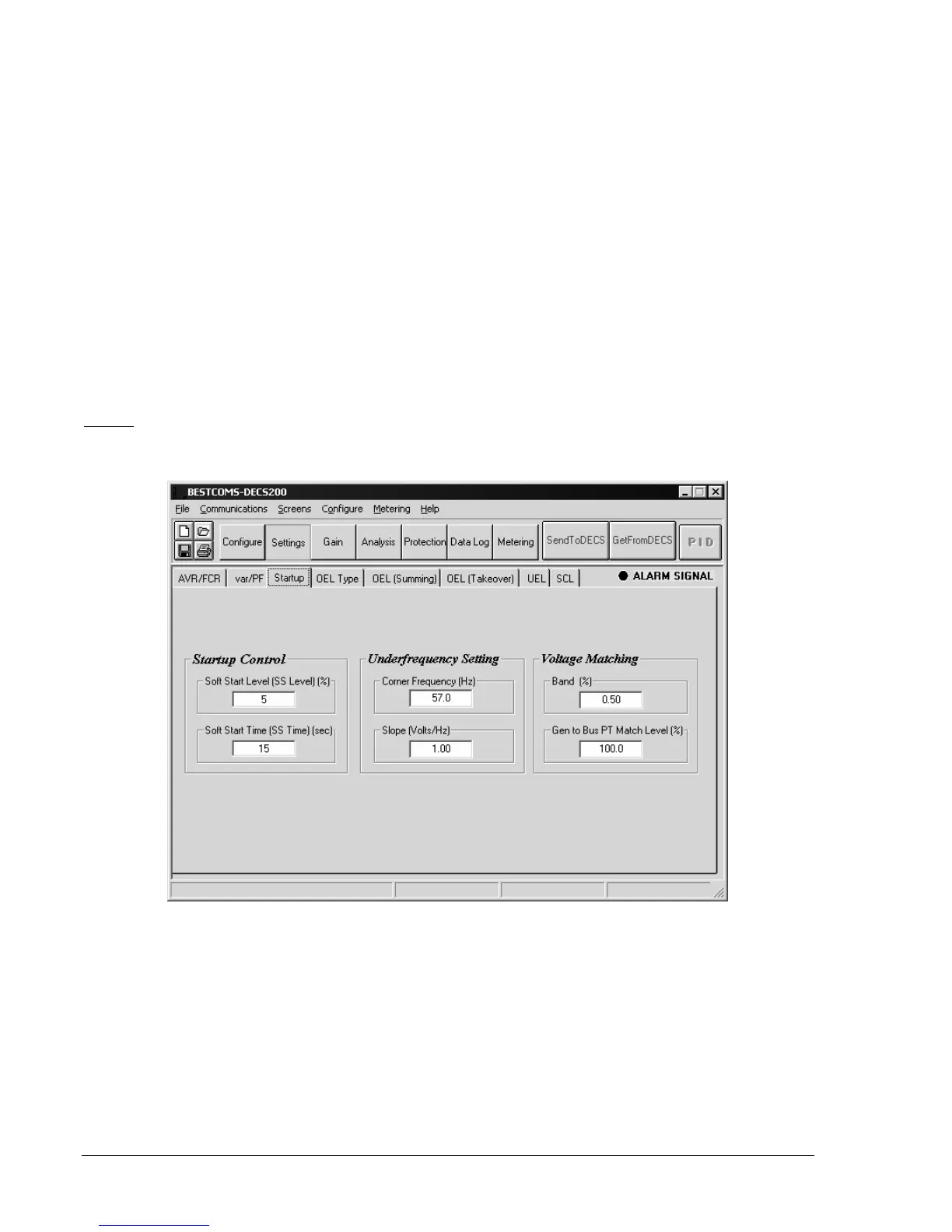
Configure the startup control, underfrequency, and voltage matching settings illustrated in Figure 6-7.
Figure 6-7. Startup Tab
Enter the soft-start voltage offset used during startup .................................................................. ________
Enter the soft-start time limit used during startup ......................................................................... ________
Enter the corner frequency for generator underfrequency protection........................................... ________
Enter the generator frequency slope for underfrequency protection ............................................ ________
Enter the voltage matching band, expressed as a percent of the rated generator voltage .......... ________
Enter the ratio (percentage) of the generator PT output to the bus PT output ............................. ________