Figure 3.11 Optical bench view
43
44
45
42
41
Figure 3.12 Optical bench view
48
49
50
47
46
52
53
54
55
56
51
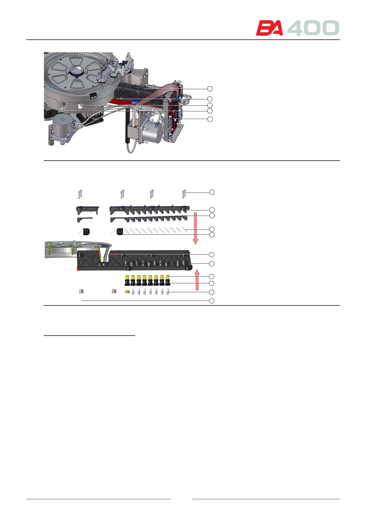
References of gures 3.11 and 3.12
41 – Optical bench
42 – CIIM00051 board
43 – Cover sensor
44 – Temperature sensor
45 – CIIM000050 board
46 – Optical bench opening screws
47 – Optical bench cover
48 – Optical bench seal
49 – Beamsplitters for each wavelength
50 – Lenses and lens holder
51 – Rotor
52 – Optical bench support
53 – Filters for each wavelength
54 – Filter holder
55 – Leds for each wavelength
56 – Principal and reference photosensors
e optical bench is secured directly to board CIIM00051 (42). e dierent leds (55) for each wavelength and the
main and reference photodiodes (56) are welded to board CIIM00051 (42). e lters (53) for each wavelength
are inserted in the lter holders (54) and screwed to the optical bench support (52). To ensure that the light beam
for each wavelength hits the rotor (51) there are beam splitters (49) and lenses (50). e whole assembly is sealed
by a rubber joint (48) and a cover (47).
25