Service Manual
51
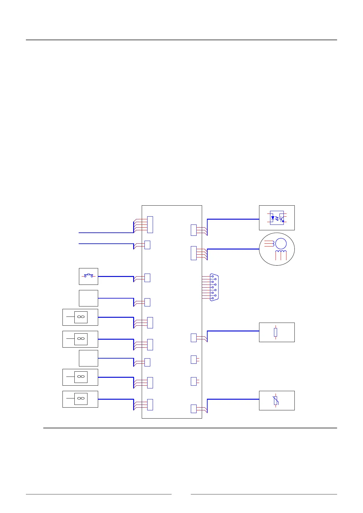
• Rotor motor (U8)
• Rotor start-up detection (U3)
• Barcode reading communication (U3 and U4)
Fridge components mounted on the reagent rotor board
• Separate power supply (U16)
• Micro controller (U13)
• Reading window demisting driver (U10 and U17)
• ermistor for controlling fridge
• Fridge peltier control (U9 and U11)
• Fridge peltier fans (U9 and U11), controlled by the same drivers as the peltiers
CIIM00052
CAN BUS
ROTOR
DETECTOR
ROTOR
MOTOR
A-PLMA00337
PLMA00345
SENSOR
FAN3
FAN4
PELTIER
BRANCH2
FRIDGE
FAN
FAN1
FAN2
PELTIER
BRANCH1
COVER
DETECTOR
A-PLMA00335
HEATER
FA FRIDGE
PLMA00338
FRIDGE SUPPLY
CN4
FRIDGE
FAN
FRIDGE
FAN
FRIDGE
FAN
CAN BUS
B-PLMA00332
B-PLMA00333
B-PLMA00334
THERMISTOR
DEFOGGER
A-PLMA00336
BARCODE
READER
BARCODE
READER
ROTOR HOME
ROTOR
CIIM00052-A : REAGENT
CIIM00052-B : SAMPLE
COOLER
POWER
SUPPLY
ROTOR COVER
ROTOR COVER
PELTIERS
BRANCH2
PELTIERS
BRANCH2
P.FAN4
P.FAN3
P.FAN2
P.FAN1
THERMISTOR
DEFOGGER
ROTOR
ROTOR
HOME
CN15CN15
1
2
3
1 2
CN6CN6
1
2
CN14CN14
1
2
3
CN16CN16
1
2
CN26CN26
1
2
3
4
5
CN16CN16
1
2
3
CN8CN8
1
2
CN19CN19
1
2
3
12
+tº+tº
12
1
2
3
4
5
6
CN3CN3
1
2
CN13CN13
1
2
1 6
2
5
4
CN2CN2
1
2
CN7CN7
1
2
CN11CN11
1
2
3
RS-232 -BAR CODE READINGRS-232 -BAR CODE READING
5
9
4
8
3
7
2
6
1
CN12CN12
1
2
CN9CN9
1
2
3
4
Figure 4.15 Rotor board connections