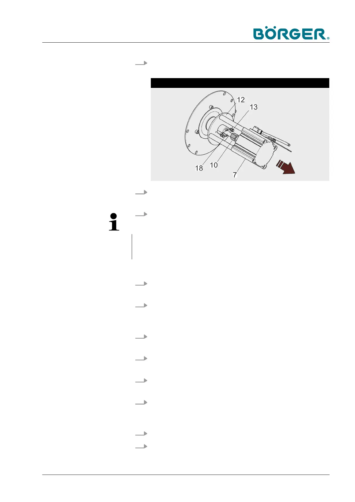
6. Loosen the two hexagon head screws (13) at the plate of the
pneumatic cylinder unit (12).
Remove the pneumatic cylinder unit
7. Loosen the threaded adapter (10) at the threaded rod (18)
using a 30 mm hexagon socket wrench.
8.
NOTE!
Ensure that a second person holds the pneumatic cylinder
unit (7) when the hexagon head screws (13) are loosened.
ð
Remove the pneumatic cylinder unit (7).
9. Check the pneumatic cylinder. Replace the pneumatic cyl-
inder if it shows signs of damage.
10. Slide the pneumatic cylinder unit (7) onto the threaded rod
(18) and tighten the threaded adapter (10) at the same time
using a 30 mm hexagon socket wrench.
11. Tighten the two hexagon head screws (13) at the plate of the
pneumatic cylinder unit (12).
12. Install the cover (8) of the clamping unit and tighten the hex-
agon socket head cap screws (9).
13. Attach the compressed-air tube (7.1) to the plate (5) with the
rotating union (6).
14. Push the plate with the rotating union (6) and the com-
pressed-air tube (7.1) into the cover (8) so that the plate (5)
sits firmly on the cover (8).
15. Tighten the hexagon head screws with washers (3).
16. Attach the compressed-air tube (2) of the compressed-air
container (1) to the elbow union (3) of the clamping unit.
Maintenance and repairs
BA-RC40_EN, 17.01.2024 www.boerger.de / www.boerger.com 135