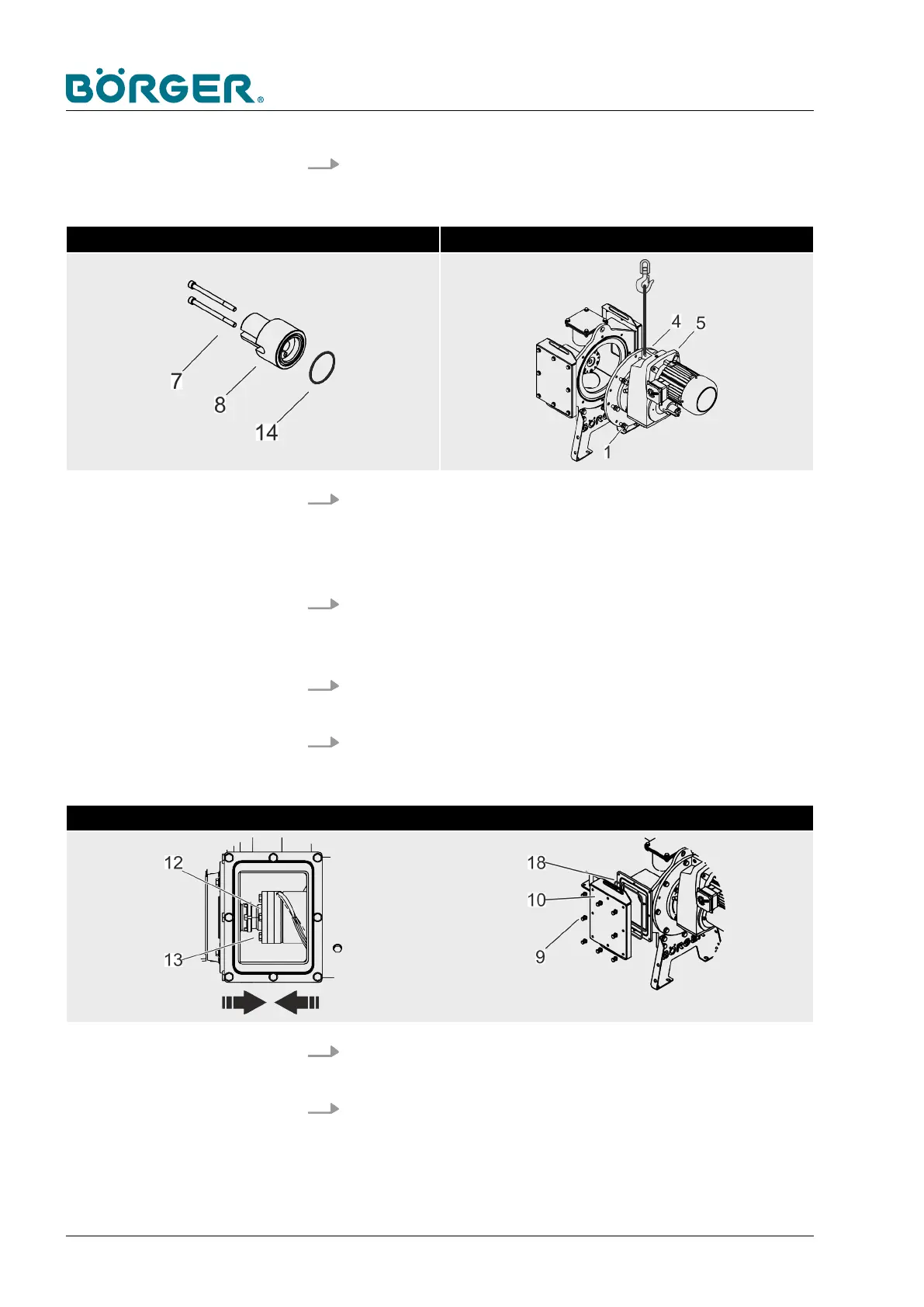
15. Install the spring guide bolt (8) with the O-ring (14) and
tighten the two hexagon socket head cap screws (7) at the
spring guide bolt (8).
Install the spring guide bolt Install the drive and the motor plate at the pipe casing
16. Attach the unit consisting of the drive (5), the O-ring (3) and
the motor plate (4) to the pipe casing (2) using an appropriate
hoist and tighten the eight hexagon head screws (1) with
washers at the motor plate (4).
17. Close the screw plug (5b) and fill the intermediate chamber
with quench fluid through the fill hole (5a). Adhere to
Ä
Chapter 6.2 “Maintenance and inspection” on page 120.
18.
Connect the drive flange as detailed in
Ä
Chapter 6.3.7
“Replacing the brush auger” on page 157.
19. Install the drive pin, the drive sleeve and the threaded rod as
detailed in
Ä
Chapter 6.3.7 “Replacing the brush auger”
on page 157.
Install the drive flange Install the cover of the maintenance opening
20.
Install the Multi Disc as described in
Ä
Chapter 6.3.4
“Changing the Multi Disc plate” on page 146.
21.
Attach the clamping unit as described in
Ä
Chapter 6.3.2
“Removing/repairing the clamping unit” on page 131.
Maintenance and repairs
BA-RC40_EN, 17.01.2024www.boerger.de / www.boerger.com144
 Loading...