BL702/704/706 Reference Manual
10.3 UART function description
10.3.1 Data format description
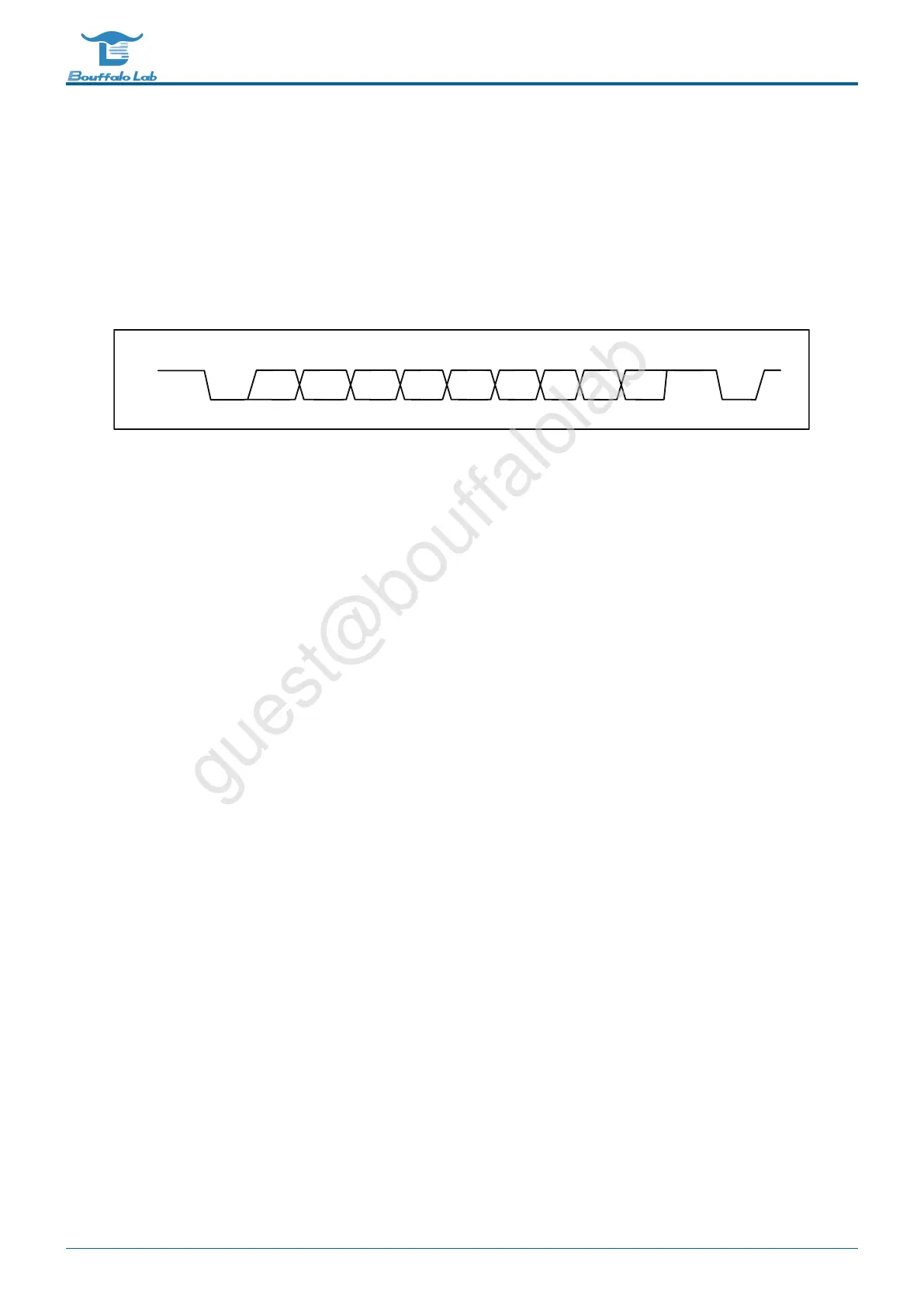
Normal UART communication data is composed of a start bit, a data bit, a parity bit, and a stop bit. The BL702’s UART
supports configurable data bits, parity bits, and stop bits, all of which are set in the UTX_CONFIG and URX_CONFIG
registers. The waveform of one frame of data is shown below:
8bit Single data length + Odd parity
bit 0 bit 1 bit 2
StartStart
odd
Stop
bit 7bit 6bit 5
bit 4bit 3
Fig. 10.1: UART data
The start bit of a data frame occupies 1-bit, and the stop bit can be configured to be 0.5 / 1 / 1.5 / 2 bits wide by
configuring <TXBCNTP> and <CR_URX_BIT_CNT_P>. The start bit is low and the stop bit is high.
The data bit width can be configured to 5/6/7/8 bit width by <TXBCNTD> and <RXBCNTD>.
When <TXPREN> and <RXPREN> are set, the data frame adds a parity bit after the data. <TXPRSEL> and <RX-
PRSEL> are used to select odd or even parity. When the receiver detects a parity error in the input data, a parity
error interrupt is generated.
Odd parity calculation method: If the current data bit 1 is an odd number, the odd parity bit is 0; otherwise, it is 1.
Calculation method of even parity: If the number of current data bit 1 is odd, even parity is 1; otherwise it is 0.
10.3.2 Clock source
The UART has two clock sources: 96MHz PLL_CLK and FCLK. The frequency divider in the clock is used to divide
the clock source and then generate a clock signal to drive the UART module. As shown below:
BL702/704/706 Reference Manual 190/ 375
@2021 Bouffalo Lab