13
TIMER
13.1 TIMER introduction
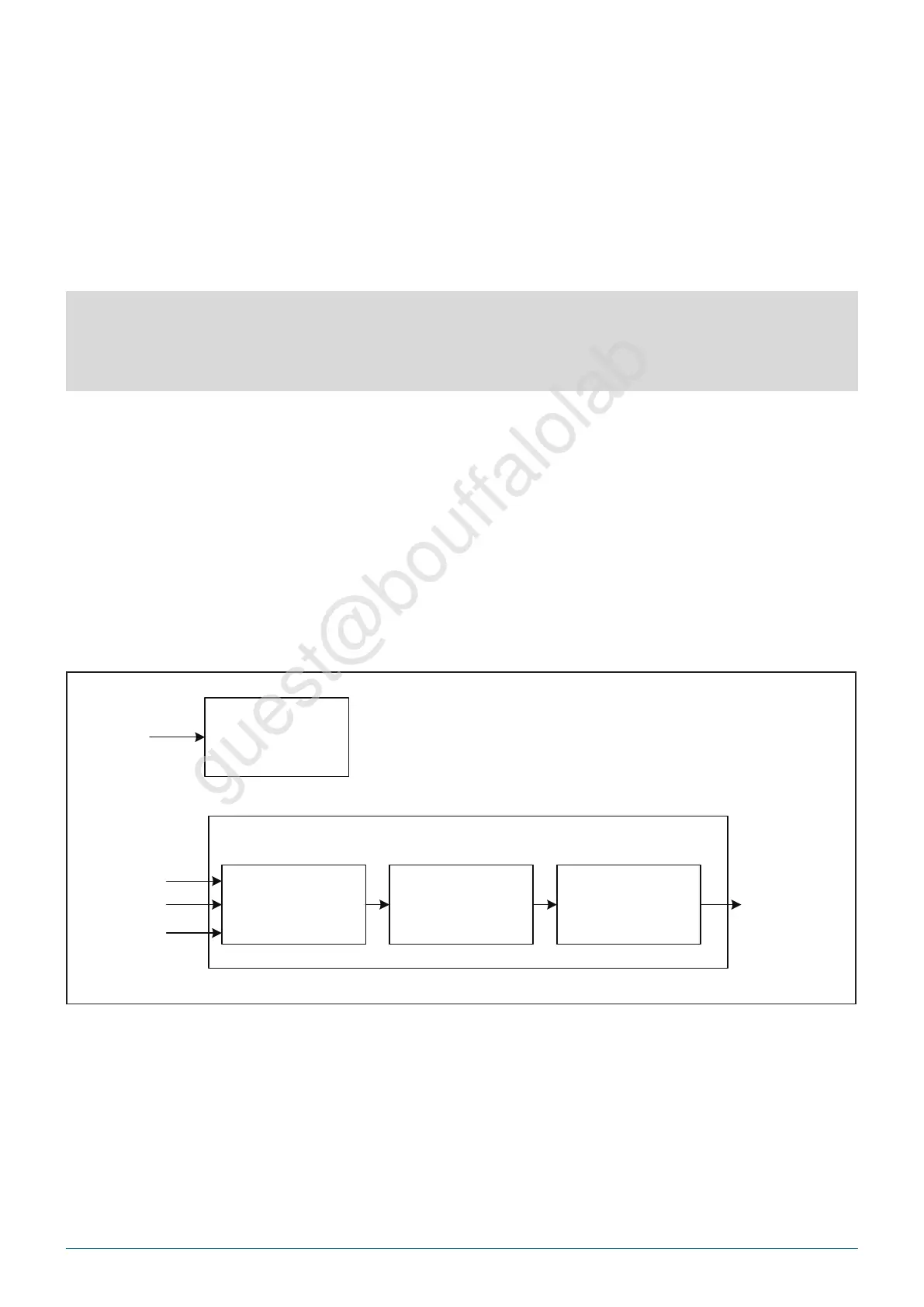
The chip has two 32-bit counters, each of which can independently control and configure its parameters and clock
frequency.
There is a watchdog counter in the chip. Unpredictable software or hardware behavior may cause the application to
malfunction. A watchdog timer can help the system recover from it. If the current time exceeds the predetermined
time, but the dog is not fed or closed Timer, which can trigger interrupt or system reset according to the setting.
BL_TIMER
AP
B
CSR
timer_irq
32-bit timer
fclk
clk_mux clk_div timer_cntxtal_
f32k
_
X2
clk
clk
Fig. 13.1: Timer block diagram
BL702/704/706 Reference Manual
240/ 375
@2021 Bouffalo Lab