BL702/704/706 Reference Manual
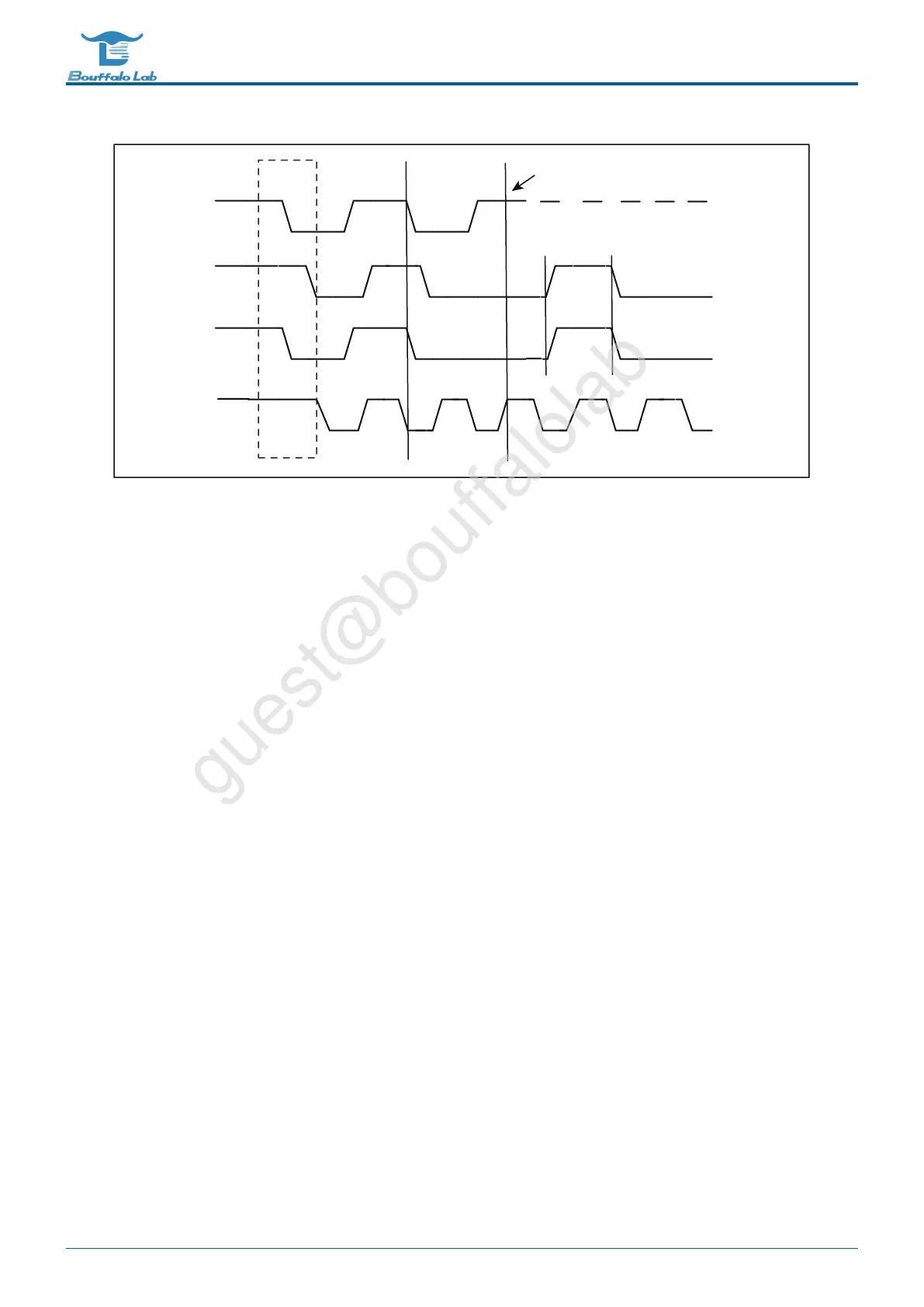
DATA1
DATA2
SDA
SCL
S
master 1 loses arbitration
DATA 1 ≠ SDA
Fig. 11.5: Tx and Rx together
11.4 I2C clock setting
The I2C clock is derived from bclk (bus clock), which can be divided based on the bclk clock.
Register I2C_PRD_DATA can divide the clock of the data segment. The i2c module divides the data transmission
into 4 phases. Each phase is controlled by a single byte in the register. The number of samples in each phase can
be set. The 4 samples together determine the frequency division coefficient of the i2c clock. .
For example, bclk is 32M and the value of register I2C_PRD_DATA is 0x0f0f0f0f by default without configuration.
Then the clock frequency of I2C is 32M / ((15 + 1) * 4) = 500K.
Similarly, the registers I2C_PRD_START and I2C_PRD_STOP also divide the clock of the start bit and stop bit re-
spectively.
11.5 I2C configuration process
11.5.1 Configuration item
• Read and write flags
• Slave address
• Slave device address
• Slave device address length
• Data (when sending, configure the data to be sent; when receiving, store the received data)
• Data length
BL702/704/706 Reference Manual 210/ 375
@2021 Bouffalo Lab