BL702/704/706 Reference Manual
3.2.7 GPIO function description
Each GPIO can be configured by software as:
• Multiple functions: I2S, SPI, I2C, UART, PWM, USB, SWGPIO... up to 24 functions
• InputEnable/OutputEnable: input, output, high impedance (ie=0, oe=0)
• PullUp/PullDown: pull up, pull down, float (pu=0, pd=0)
• drive strength: four gears of 0, 1, 2, and 3. The larger the value, the stronger the drive ability
• smt trigger: smt enable, smt disable, to prevent jitter near the trigger threshold
When the GPIO multiplexing function is configured as SWGPIO input, you can also configure the interrupt trigger mode for
it, and each GPIO can have two interrupt modes, and both interrupt modes can be effective separately/simultaneously:
• Interrupt mode 1: rising edge trigger, falling edge trigger, high level trigger, low level trigger
• Interrupt mode 2: rising edge trigger, falling edge trigger, high level trigger, low level trigger
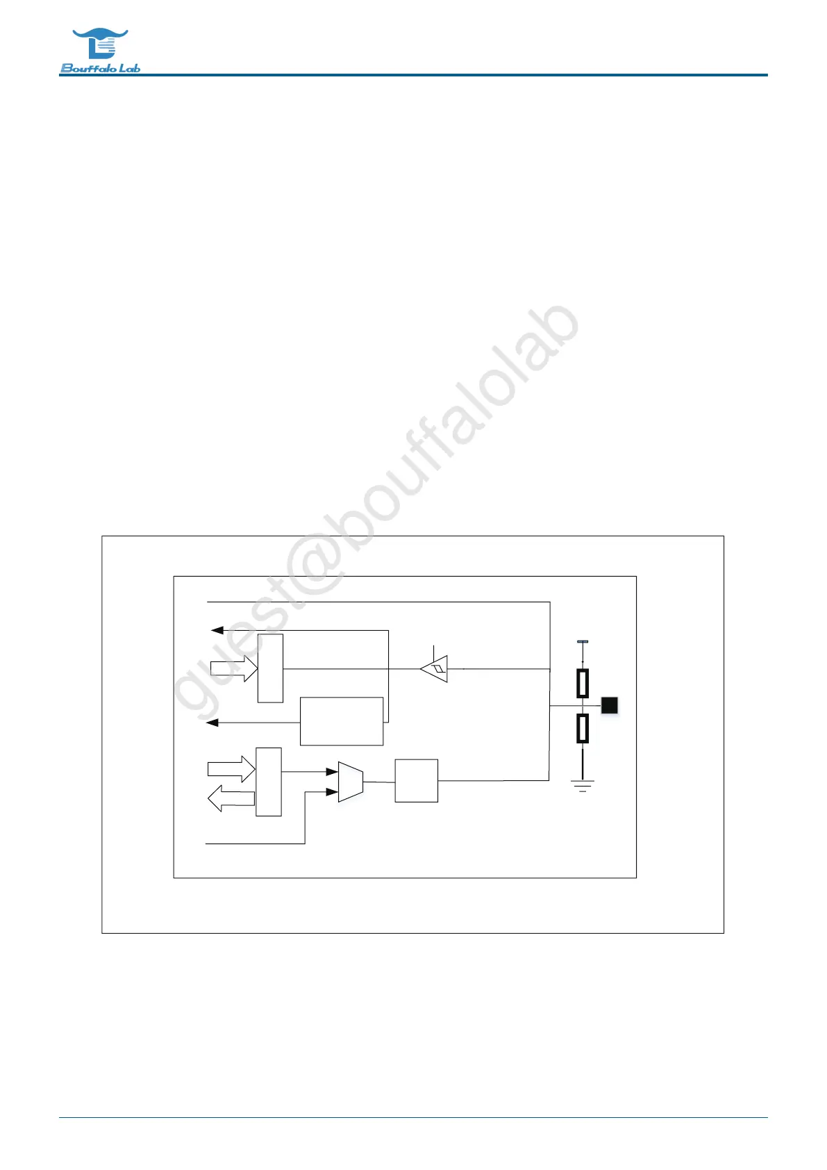
The basic block diagram of the GPIO module is shown in the figure.
ON/OFF
output
control
input register
output register
peripheral optional function input
analog input/RXWSXW
bus read
bus write
interrupt detection
and control
interrupt inout
Rd
Ru
GND
VCC
bus read
peripheral optional function output
Fig. 3.1: Basic block diagram of GPIO
BL702/704/706 Reference Manual 32/ 375
@2021 Bouffalo Lab