BL702/704/706 Reference Manual
12.3.2 Pulse generation principle
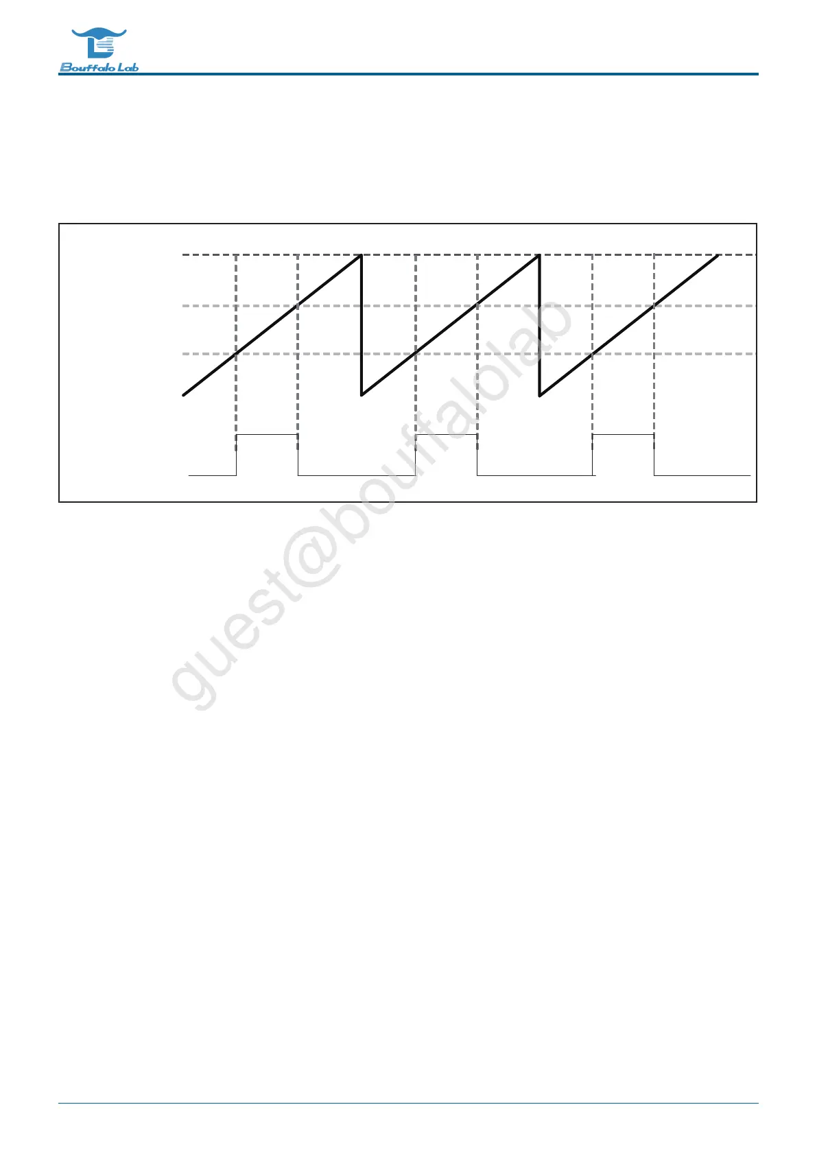
There is a counter in the PWM. When the counter is in the middle of two settable thresholds, the PWM output is 1,
otherwise when the counter is outside the two set thresholds, the PWM output is 0. As shown below:
Threshold 1
Threshold 2
Internal counter
Period
PWM output
Fig. 12.1: PWM waveform
The PWM cycle is determined by two parts, one is the clock frequency division coefficient, and the other is the clock
duration.
The clock division coefficient is set by the register PWMn_CLK_DIV[15:0] (n is 0~4), which is used to divide the PWM
source clock.
The clock duration is set by the register PWMn_PERIOD[15:0] (n is 0~4), which is used to set the number of divided
clock cycles for a PWM cycle. That is, the period of PWM=PWM source clock/PWMn_CLK_DIV[15:0]/PWMn_PE-
RIOD[15:0].
The duty cycle of PWM is determined by the clock duration and two thresholds. The first threshold is set by the register
PWMn_THRE1[15:0] (n is 0~4), the second threshold is set by the register PWMn_THRE2[15:0] (n is 0~4), the PWM
waveform will be in the first Pull up at one threshold, and pull down at the second threshold. That is, the duty cycle of
PWM=(PWMn_THRE2[15:0]-PWMn_THRE1[15:0])/PWMn_PERIOD[15:0].
Example: If the PWM clock source is selected as bclk, which is 72MHz, to generate a 1kHz, 20% duty cycle PWM
wave, set as follows:
PWMn_CLK_DIV[15:0]=2
PWMn_PERIOD[15:0]=72000000/2/1000=36000
PWMn_THRE1[15:0]=0
PWMn_THRE2[15:0]=0+36000*20%=7200
BL702/704/706 Reference Manual 223/ 375
@2021 Bouffalo Lab