BL702/704/706 Reference Manual
implement multiple sampling conversions on a channel.
ADC conversion results are generally placed in the FIFO. The ADC module does not provide conversion completion
interrupts. Users need to set the FIFO receive data threshold interrupt based on the actual number of conversion
channels. The FIFO threshold interrupt is used as the ADC conversion completion interrupt.
4.3.5 ADC consequence
The gpadc_raw_data register stores the raw result of the ADC. In single-ended mode, the data valid bit is 12bits,
unsigned bit. In differential mode, the highest bit is the sign bit. The remaining 11bits represent the result of the
conversion.
The gpadc_data_out register stores the ADC result. This result contains the ADC result, sign bit and channel infor-
mation. The data format is as follows:
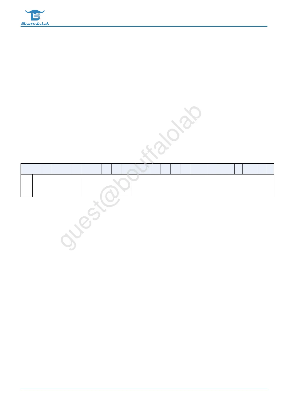
Table 4.3: ADC conversion result format
BitS 25 24 23 22 21 20 19 18 17 16 15 14 13 12 11 10 9 8 7 6 5 4 3 2 1 0
me
an
Positive channel
number
Negative channel
number
Conversion result
bit21-bit25 of the conversion result is the positive channel number, bit16-bit20 is the negative channel number, and
bit0-bit15 is the converted value.
The gpadc_res_sel control bit can set the number of bits of the conversion result, which are 12 bits, 14 bits, and
16 bits, respectively. Among them, 14 bits and 16 bits are the results obtained by multiple sampling to improve the
accuracy.
The values that can be set are as follows:
• 3’b000 12bit 2MS/s, OSR=1
• 3’b001 14bit 125kS/s, OSR=16
• 3’b010 14bit 31.25kS/s, OSR=64
• 3’b011 16bit 15.625KS/s, OSR=128
• 3’b100 16bit 7.8125KS/s, OSR=256
The ADC conversion result is left-justified. When 12 bits are selected, bit15-bit4 of the conversion result is valid.
When 14 bits are selected, bit15-bit2 of the conversion result is valid. When 16 bits are selected, bit15-bit0 of the
conversion result is valid.
Similarly, in the differential mode, the highest is the sign, that is, when 14 bits are selected, bit15 is the sign bit,
bit14-bit2 is the conversion result, and bit14 is the MSB.
BL702/704/706 Reference Manual 95/ 375
@2021 Bouffalo Lab