Brooks Automation 7. Service Procedures
Part Number: PF40-DI-00010 Rev. A Installing the Optional GIO Board
Step Action
1.
Remove the top cover plate from the top of the robot Z column by removing the (4) M5 X 10 mm
LHCS.
2.
Remove the front Z column cover by sliding it upwards through the Z carriage.
3.
Remove the left splash guard by removing the M3 X 8 mm SHCS and star washer holding the splash
guard to the robot base plate.
4.
Disconnect the Ethernet cable and move it out of the way if necessary.
5.
Remove the 25-pin Dsub blank cover plate from the connector panel by removing the M3 BHCS.
These screws are retained by M3 nylon insert hex nuts on the back of the front connector panel.
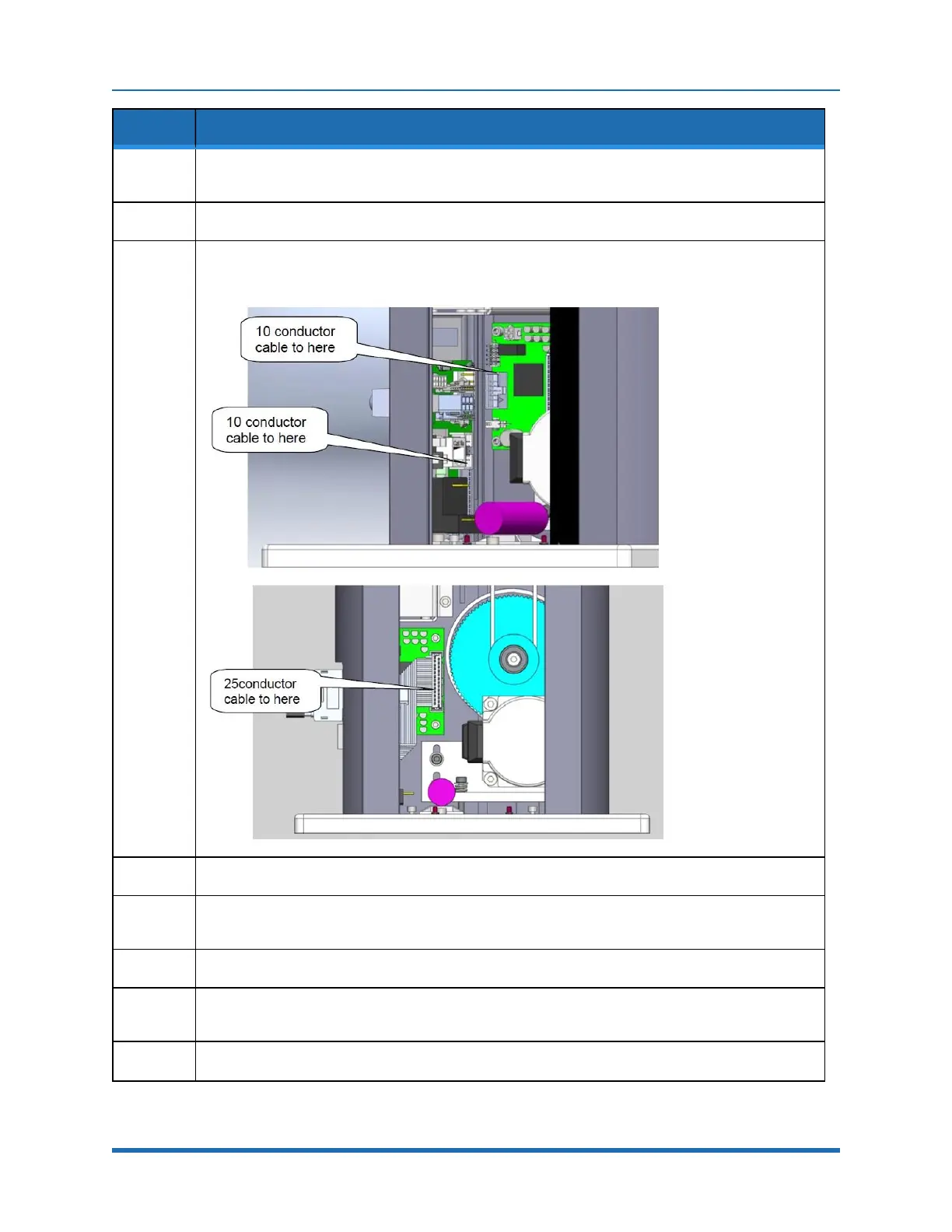
6.
Remove all (4) address jumpers on the GIO board J8-J11. See Step3.
7.
Install the GIO board with the (4) M3 X 10 mm SHCS on the rear surface of the Z column as shown
in Step3.
8.
Install the 10 conductor RS-485 jumper cable from the GIO board to the connector panel board.
Copyright © 2023, Brooks Automation
128