7. Service Procedures (Undefined variable: MyVariables.ProductName)
Replacing the Z-axis Motor Assembly Part Number: PF40-DI-00010 Rev. A
Step Action
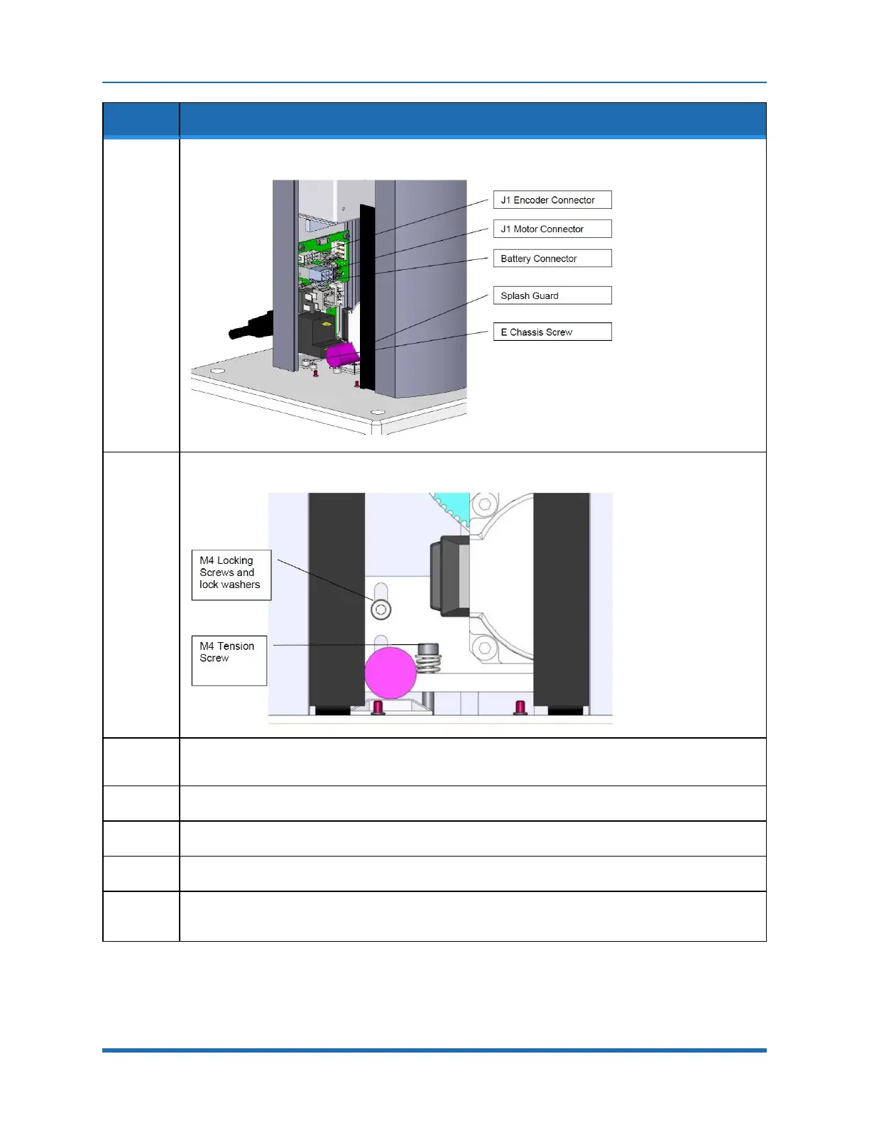
8.
Unplug the Battery from the J1 Motor Interface Board.
9.
Remove the screw compressing the J1 Motor Tension Spring and spring.
10.
Remove the Base Mounting Plate by removing the (4) M5 SHCS.
The right splash guard is attached to the base mounting plate.
11.
Remove the M4 Locking Screws that attach the J1 Motor Mount Bracket to the Z Column.
12.
Slide the J1 Stage 1 timing belt off the large idler pulley.
13.
Slide the J1 Motor and Motor Mount Bracket assembly out the bottom of the Z Column.
14.
Remove the J1 Motor Assembly from the J1 Motor Mount Bracket and replace with the new motor,
using Loctite 243.
135
Copyright © 2023, Brooks Automation