6. Software Reference (Undefined variable: MyVariables.ProductName)
Servo Gripper Controller Digital Inputs
and Outputs
Part Number: PF40-DI-00010 Rev. A
to pins 2 and 3 to connect Digital Output 3 to pin 3 and is connected to pins 1 and 2 to connect pin 3
to a line that goes back to the controller RS-232 TXD input. See Figure 6-2.
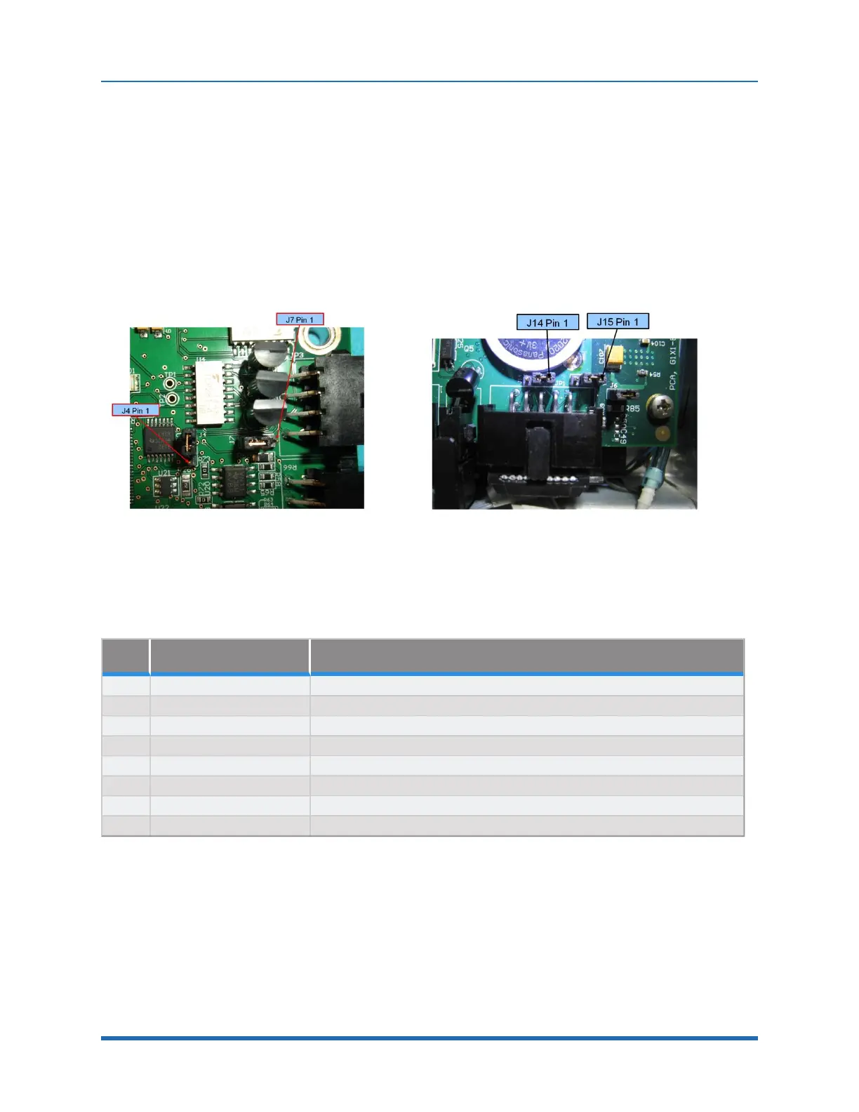
On the controller CPU board, two more jumpers must be correctly installed to connect RS-232 to the
GSB. On the CPU board, shown below, J14 and J15 must be connected to pins 2 and 3 to connect
the TXD and RXD inputs from the GSB to the serial inputs in the CPU. The factory configuration for
J14 and J15 is connecting pins 1 and 2. This is because prior to Revision 4 of the GSB, the wires
connected to these pins in the RS-485 cable were grounded, and if a user plugs in a GSB earlier
than Revision 4, they will ground the RS-232 signals unless J14 and J15 are in their factory
configuration. See Figure 6-3.
Figure 6-2: J4 and J7 on GSB Board
Figure 6-3: J14 and J15 on CPU Board
The GSB I/O signals are shown in Table 6-1.
Pin GPL Signal Number Description
1 200013 Digital Output 1
2 200014 Digital Output 2
3 200015 Digital Output 3 (LED Output or TXD, select with J7)
4 24 VDC output
5 GND
6 210001 Digital Input 1 (Pushbutton on some Electric Grippers or RXD, select with J4)
7 210002 Digital Input 2 (End of travel sensor option)
8 210003 Digital Input 3
Table 6-1: GSB I/O signals
87
Copyright © 2023, Brooks Automation