Valid from serial number T-code
713962- 403-414, 669-671, 716-718
Order number Date
218920-040 2005-06-01
© BT Europe AB Service Manual REFLEX RR B/E, RR B/E CC 2- 9
General product information – M2
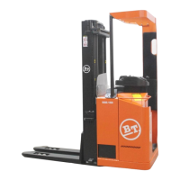
Main components RR B/E 2-8 CC
2.6 Main components
RR
B/E 2-8 CC
1. Hydraulic valves:
The valves are located to provide easy ac-
cess.
2. Battery:
48 V with different Ah values.
3. Recharging connector:
The battery is recharged via this perma-
nently attached recharging connector.
4. Control circuit fuse:
10A, part no. 161640-100.
Fuse for electrical steering wheel:
30 A, part no. 161640-300.
5. Hydraulic unit:
Pump motor, pump and oil tank integrated
in a compact unit.
6. Drive unit with brake:
Drive motor, gears and drive wheel com-
bined into a compact unit. Steering bear-
ings between motor and gears as well as a
360° steering angle which facilitates the
handling of loads.
7. Electrical steering motor:
Mounted with the drive gear to provide a
compact design.
8. Mast:
The mast is a clear-view model and is
equipped with an identification plate with
type designation, serial number and date of
manufacture.
9. Control console:
The control console can be adjusted to a
suitable height and angle to obtain a com
-
fortable working position. The steering, hy-
draulic functions, horn, parking brake,
height indication, travel direction and any
extra hydraulic functions are all controlled
from this console.
10. Operator’s seat:
The seat is fully adjustable to provide opti-
mal operator comfort.
11. Serial number:
The manufacturing number plate fitted to
the chassis.
12. Instrument panel:
This provides information on the truck’s
running time, time indication, error codes,
travel direction, parking brake, steering an
-
gle, operator identification and battery sta-
tus. The instrument panel also houses the
emergency switch off, key and switches for
accessories.
13. Pedals:
Accelerator with optional direction selector,
travel brake and safety pedal.
14. Heater:
The main heater for the driver's cab ena-
bles setting of the temperature and operat-
ing the auxiliary heater.
15. Control circuit fuse:
5A, part no. 161640-005.
Fuse for main heater.
30 A, part no. 161640-030.
Fuse for auxiliary heater
30 A, part no. 161640-030.
16. Identification plate, truck:
With model designation, serial number,
year of manufacture, weight without bat
-
tery, battery weight, rated capacity, battery
voltage and manufacturer.
17. Height indication
18. Electronics:
All the electronics collected in a protected
compartment.
19. Drive motor fuse:
RR E2CC-E3CC:
125 A, order no. 29584.
RR E4CC-E8CC:
160 A, order no. 29223.
20. Pump motor fuse:
RR E2CC-E3CC:
200 A, order no. 29673.
RR E4CC-E6CC:
250 A, order no. 29221.
RR E7CC-E8CC:
300 A, order no. 29674.
https://www.forkliftpdfmanuals.com/