2-106 2007 Buell Lightning: Chassis
HOME
ASSEMBLY
1. See Figure 2-133. Install sidestand leg (1).
a. Lubricate sidestand pivot pin and mating portions on
sidestand bracket with WHEEL BEARING GREASE
(Part No. 99855-89) as shown in Figure 2-134.
b. See Figure 2-133. Install sidestand leg (1) to bracket
(5) by installing the pivot pin (3) and pivot pin circlip
(7).
c. Retract sidestand leg.
d. Install spring extension plate (4) and sidestand
spring (2) using SNAP-ON SPRING TOOL (Part No.
HE-52B).
NOTE
Extension plate should curve away from primary chain adjust-
ment screw to allow for clearance around adjustment screw.
INSTALLATION
1. See Figure 2-133. Apply LOCTITE 271 (red) to the side-
stand bracket fasteners (6). Loosely install the sidestand
assembly to the crankcase with the sidestand bracket
fasteners (6).Extend the sidestand leg (1) and hold for-
ward in the fully extended position while tightening the
sidestand bracket fasteners (6) in the following
sequence:
a. Tighten the front fastener to 25-27 ft-lbs (34-37 Nm).
b. Tighten the rear fastener to 25-27 ft-lbs (34-37 Nm).
2. Repeat the tightening sequence Step 1 to verify proper
clamp load.
3. Install muffler. See Muffler and Straps in 2.32 EXHAUST
SYSTEM.
4. Install chin fairing fasteners. See 2.37 CHIN FAIRING.
5. Extend and retract sidestand leg to check for proper
operation.
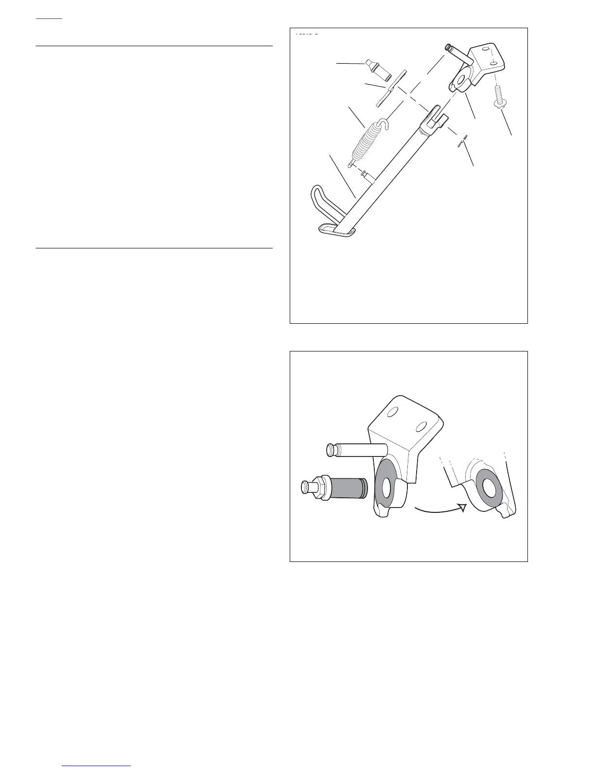
Figure 2-133. Sidestand Assembly
Figure 2-134. Lubricating Points (Shaded Areas)
1. Leg
2. Spring
3. Pivot pin
4. Extension plate
5. Bracket
6. Bracket fastener (2)
7. Pivot pin circlip
b0946x2x
3
b0964g2x
2
1
4
5
6
7
b1128c3x