2007 Buell P3: Chassis 2-29
HOME
DISASSEMBLY
1. See Figure 2-39. Use BRAKE CALIPER PISTON
REMOVER (Part No. B-42887) to pull the two pistons
from caliper bores.
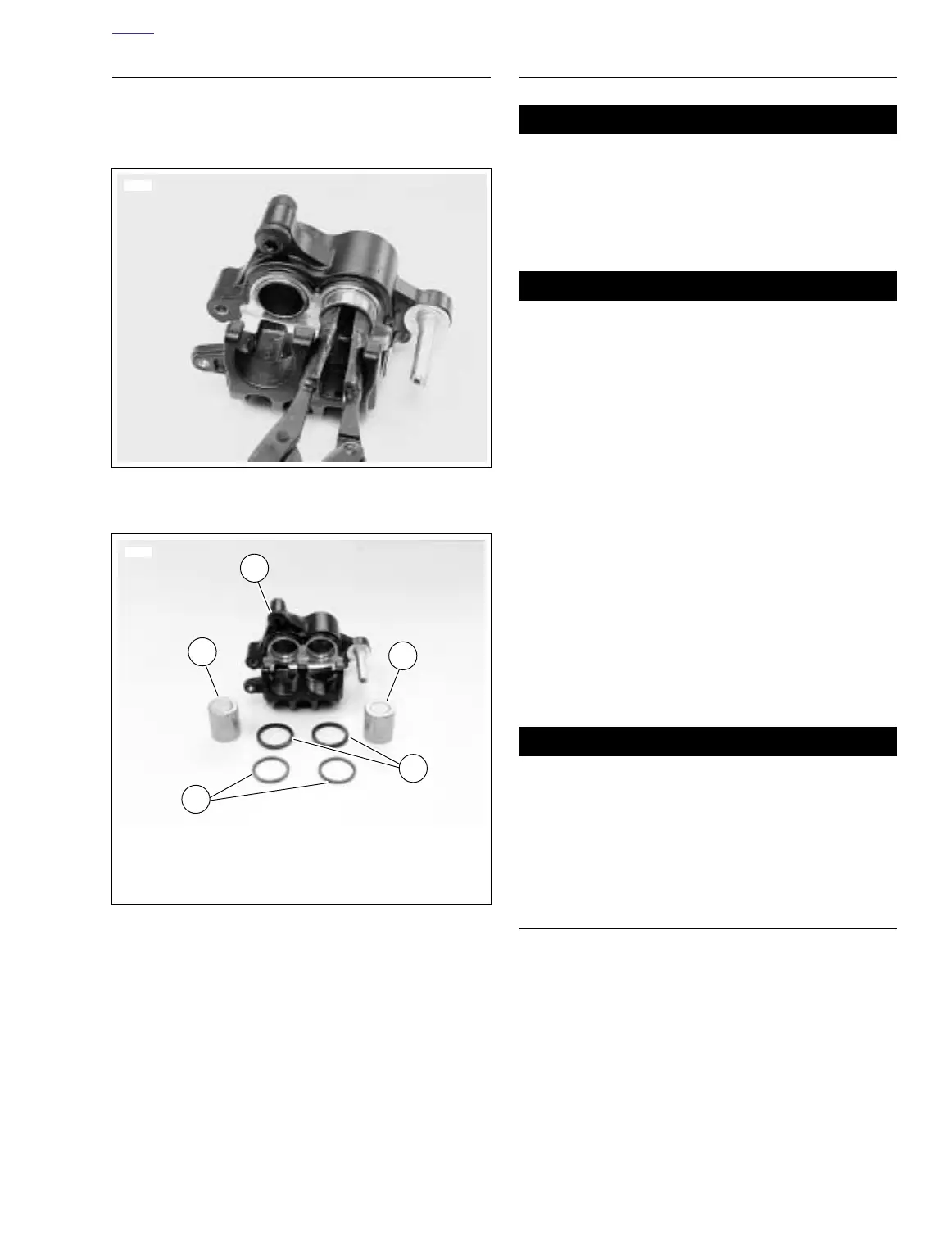
2. See Figure 2-40. Remove piston outer seals (4) and
inner seals (3) from their respective grooves in caliper.
Discard seals.
3. Check bleeder valve (metric). Remove and replace if
damaged.
CLEANING AND INSPECTION
Use denatured alcohol to clean brake system compo-
nents. Do not use mineral-based solvents (such as gaso-
line or paint thinner), which will deteriorate rubber parts
even after assembly. Deterioration of these components
can cause brake failure, which could result in death or
serious injury. (00291a)
Compressed air can pierce the skin and flying debris from
compressed air could cause serious eye injury. Wear
safety glasses when working with compressed air. Never
use your hand to check for air leaks or to determine air
flow rates. (00061a)
1. Clean all parts with denatured alcohol or D.O.T. 4
BRAKE FLUID. Do not contaminate with mineral oil or
other solvents. Wipe dry with a clean, lint free cloth. Blow
out drilled passages and bore with a clean air supply. Do
not use a wire or similar instrument to clean drilled pas-
sages.
2. Carefully inspect all components. Replace any parts that
appear damaged or worn. Do not hone caliper piston
bore.
3. Inspect brake rotor.
a. Measure rotor thickness. Replace if minimum thick-
ness is less than 0.180 in. (4.5 mm).
b. Check rotor surface. Replace if warped or badly
scored.
Always replace brake pads in complete sets for correct
and safe brake operation. Improper brake operation
could result in death or serious injury. (00111a)
4. Inspect brake pads for damage or excessive wear.
Replace both pads as a set if the friction material of
either pad is worn to 0.040 in. (1.0 mm) or less.
ASSEMBLY
1. See Figure 2-40. Install pistons and O-rings.
a. Apply a light coat of D.O.T. 4 BRAKE FLUID to
seals, pistons and caliper piston bores.
b. Install two new seals (4) in outer grooves of each
piston bore.
c. Install two new seals (3) in inner grooves of each
piston bore.
d. Install pistons (2) in each piston bore.
2. Install a new bleeder valve (metric) if necessary. Tighten
to 36-60 in-lbs (4-7 Nm).
Figure 2-39. Removing Pistons
Figure 2-40. Caliper O-rings and Pistons
7699
7700
1
2
2
3
4
1. Caliper
2. Piston (2)
3. Inner seals
4. Outer seals