2-74 2007 Buell P3: Chassis
HOME
REAR ISOLATOR
Removal
1. Remove seat. See 2.28 SEAT.
11WARNING1WARNING
Disconnect negative (-) battery cable first. If positive (+)
cable should contact ground with negative (-) cable con-
nected, the resulting sparks can cause a battery explo-
sion, which could result in death or serious injury.
(00049a)
2. Remove battery. See 7.16 BATTERY.
3. Support rear of motorcycle.
4. Remove rear shock. See 2.15 REAR SHOCK
ABSORBER.
5. Remove muffler and support motor with jack. When iso-
lator is detached powertrain may move. See 2.20
EXHAUST SYSTEM
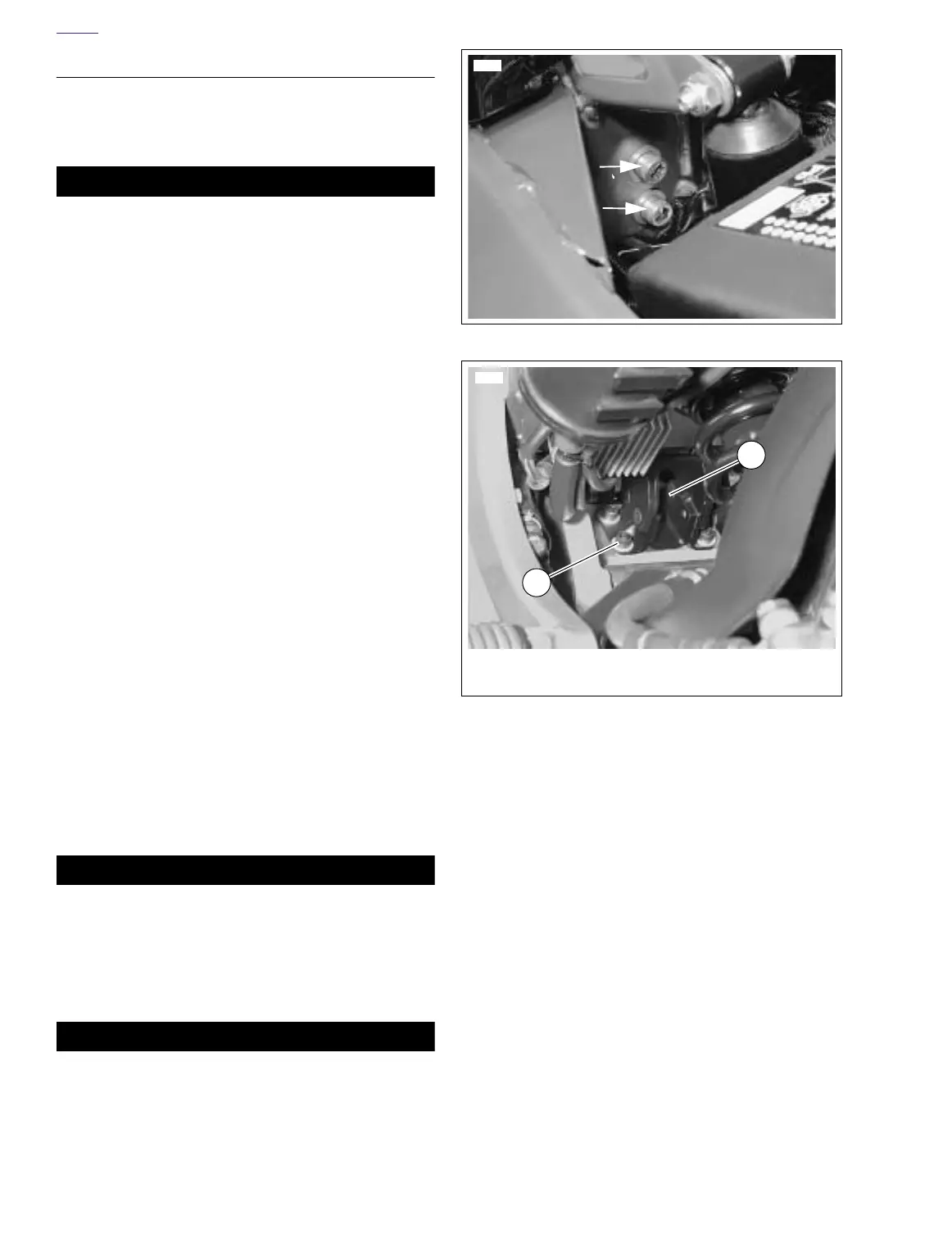
6. See Figure 2-122. Remove two allen bolts connecting
frame to isolator.
7. See Figure 2-123. Remove four bolts (2) connecting iso-
lator (1) to engine.
NOTE
It may be necessary to raise or lower motorcycle to remove
isolator.
Installation
1. See Figure 2-123. Clean engine bolt holes and bolts. Do
not re-tap holes.
2. Apply Loctite 243 (blue) to bolts and install four isolator-
to-engine bolts. Tighten bolts to 23-27 ft-lbs (31.2-
36.6 Nm).
3. See Figure 2-122. Apply Loctite Threadlocker 271 (red)
to the two frame-to-isolator bolts. Tighten bolts to 30-33
ft-lbs (41-45 Nm).
4. Install rear shock absorber. See 2.15 REAR SHOCK
ABSORBER.
11WARNING1WARNING
Connect positive (+) battery cable first. If positive (+)
cable should contact ground with negative (-) cable con-
nected, the resulting sparks can cause a battery explo-
sion, which could result in death or serious injury.
(00068a)
5. Install battery. See 7.16 BATTERY.
11WARNING1WARNING
After installing seat, pull upward on front of seat to be
sure it is in locked position. While riding, a loose seat can
shift causing loss of control, which could result in death
or serious injury. (00070a)
6. Install seat. See 2.28 SEAT.
Figure 2-122. Frame-to-Isolator Bolts
Figure 2-123. Rear Engine Mount Isolator
7745
7743
2
1
1. Rear isolator
2. Bolts (4)