2007 Buell P3: Engine 3-23
HOME
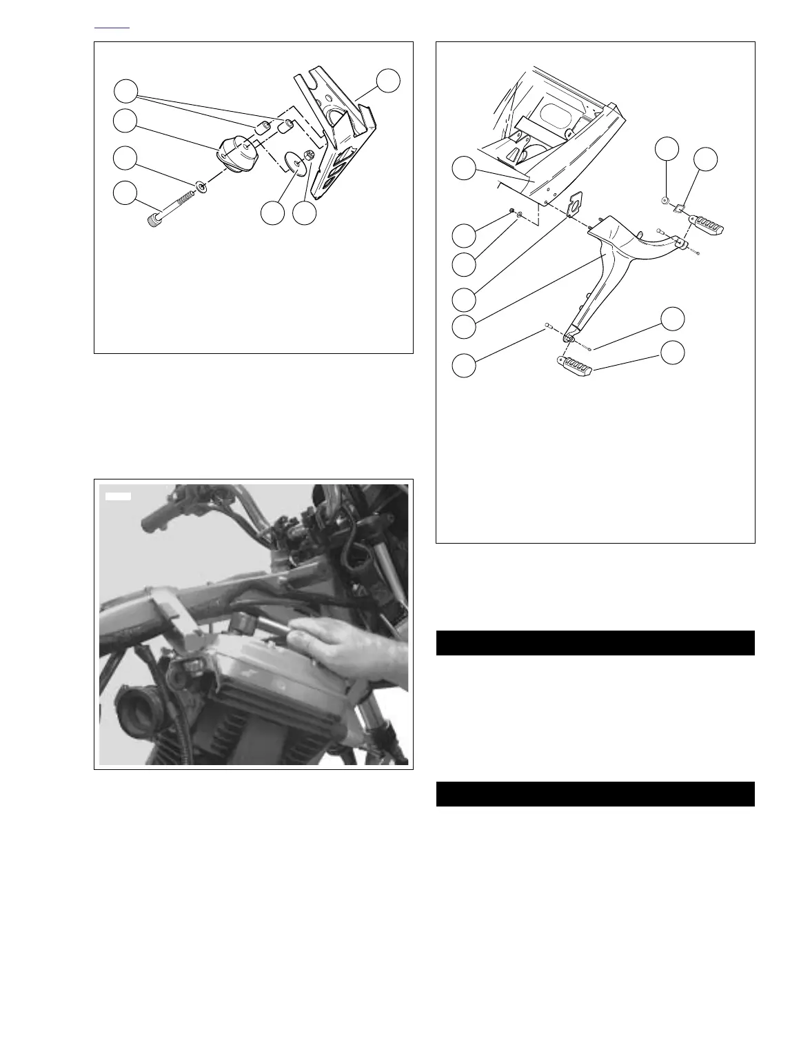
32. See Figure 3-41. Install front isolator mounting bolt,
spacer snubber and new nut.
33. Tighten front isolator mounting bolt to 63-70 ft-lbs (86-95
Nm).
34. See Figure 3-42. Install crankcase breather hose and
crankcase breather into rocker box grommet.
35. Install horn. See 7.22 HORN.
36. Remove jack from under the motor.
37. Install muffler. See 2.20 EXHAUST SYSTEM.
38. Install fuel tank. See 4.2 FUEL TANK COVER/FUEL
TANK.
39. Install new oil filter, engine oil and primary chaincase
fluid as necessary.
40. See Figure 3-43. Install right side rider footpeg bracket
assembly. See 2.21 FOOTPEGS AND FOOTPEG SUP-
PORT BRACKETS.
Connect positive (+) battery cable first. If positive (+)
cable should contact ground with negative (-) cable con-
nected, the resulting sparks can cause a battery explo-
sion, which could result in death or serious injury.
(00068a)
41. Connect both battery cables, positive cable first. See
7.16 BATTERY.
After installing seat, pull upward on front of seat to be
sure it is in locked position. While riding, a loose seat can
shift causing loss of control, which could result in death
or serious injury. (00070a)
42. Install seat. See 2.28 SEAT.
Figure 3-41. Front Isolator Mount
Figure 3-42. Install Crankcase Breather Hose
1. Frame
2. Locknut
3. Snubber
4. Bolt
5. Spacer
6. Front isolator
7. Standoff
1
a0162x6x
2
4
5
6
7
3
7629
Figure 3-43. Footpeg Bracket Assembly
1. Frame
2. Locknut
3. Washer
4. Spacer
5. Footrest support bracket
6. Clevis pin
7. Footpeg
8. Cotter pin
9. Index plate
10. Spacer
a0016x3x
1
2
3
4
5
6
7
10
9
8