3-64 2007 Buell P3: Engine
HOME
REMOVAL/DISASSEMBLY
11WARNING1WARNING
Compressed air can pierce the skin and flying debris
from compressed air could cause serious eye injury.
Wear safety glasses when working with compressed air.
Never use your hand to check for air leaks or to deter-
mine air flow rates. (00061a)
1. See Figure 3-103. Thoroughly clean area around gear-
case cover and tappets. Blow loose dirt from crankcase
with compressed air.
2. Remove any parts that will interfere with gearcase disas-
sembly.
3. See 3.5 CYLINDER HEAD. Remove push rods.
4. See 3.14 HYDRAULIC LIFTERS. Remove hydraulic lift-
ers.
5. Check for minimum cam gear end play. Record readings.
6. See 7.8 IGNITION MODULE AND CAM POSITION
SENSOR. Remove cam position sensor and rotor from
gearcase cover.
7. Place a pan under gearcase to collect oil. Remove cover
screws. Carefully remove gearcase cover. Discard old
gasket.
NOTE
If cover does not come loose on removal of screws, tap lightly
with a plastic hammer. Never pry cover off.
8. Remove cam gears.
NOTE
Nut is secured by Loctite Threadlocker 271 (red) on the nut
threads.
9. Remove nut. Slide pinion gear and oil pump drive gear
off pinion shaft.
CLEANING AND INSPECTION
1. Thoroughly clean gearcase compartment, gearcase
cover and gears in solvent to remove oil and carbon
deposits.
11WARNING1WARNING
Compressed air can pierce the skin and flying debris
from compressed air could cause serious eye injury.
Wear safety glasses when working with compressed air.
Never use your hand to check for air leaks or to deter-
mine air flow rates. (00061a)
2. Blow out all cover oil passages and bushings with com-
pressed air.
3. Clean old gasket material from gearcase and cover faces
with cleaning solvent.
NOTE
Prior to changing any cam gears, check gear shaft fit within
corresponding bushings. Worn bushings can cause excessive
backlash.
Bushing Inspection
1. See Figure 3-103. Bushings are press fit in crankcase
and gearcase cover. Inspect each bushing against its
corresponding cam gear shaft or pinion gear shaft. See
Table 3-29.
NOTE
If Service Wear Limits are exceeded, replace crankcase set
and/or gearcase cover as required.
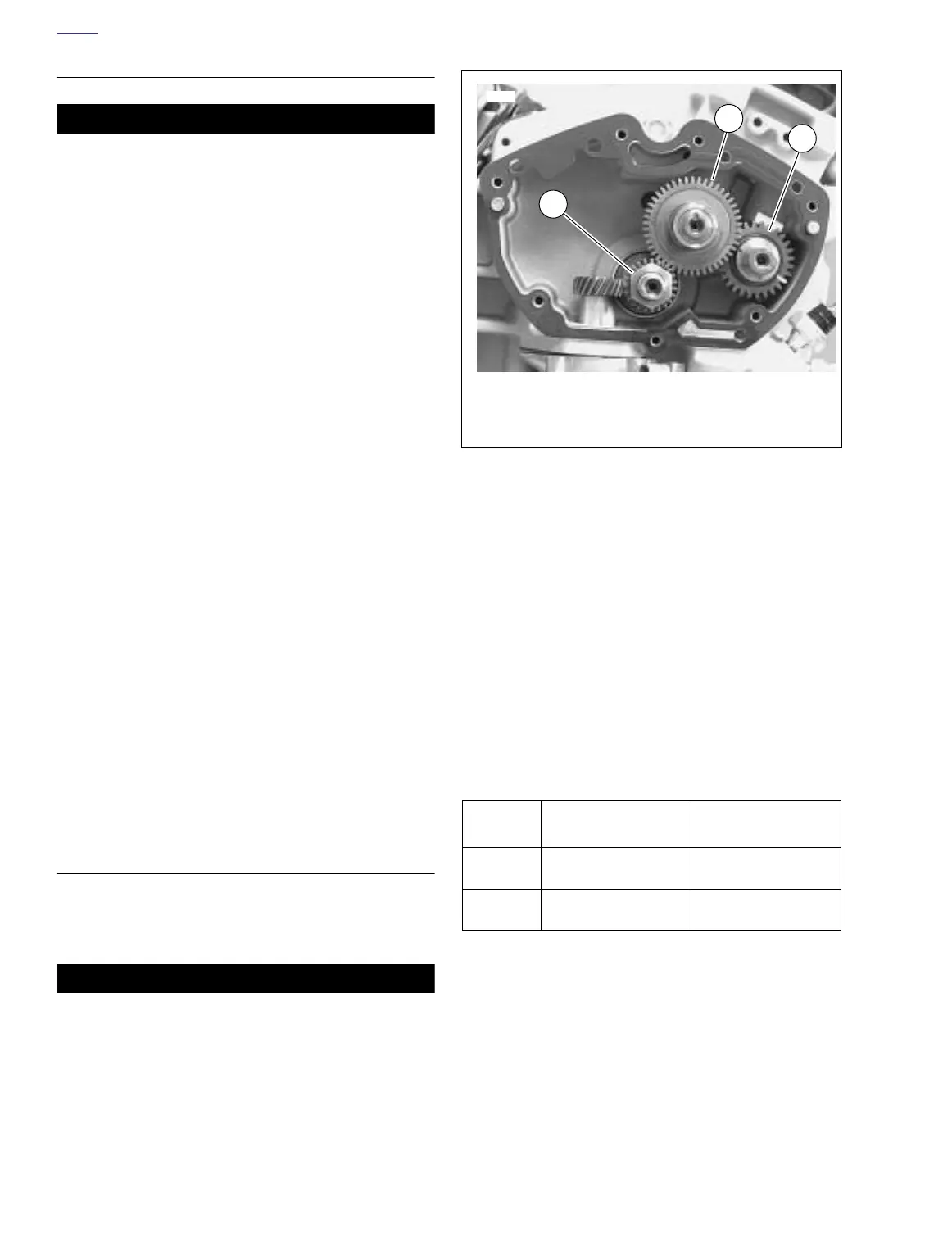
Figure 3-104. Cam and Pinion Gear Color Code Location
and Timing Mark Indexing
Table 3-29. Gear Shaft Specifications
GEAR
SHAFT
CORRECT
CLEARANCE
SERVICE WEAR
LIMIT
Cam 0.0007-0.0022 in.
(0.0178-0.0559 mm)
0.003 in.
(0.076 mm)
Pinion 0.0023-0.0043 in.
(0.0584-0.1092 mm)
0.0050 in.
(0.1270 mm)
1. Exhaust cam gear (1w)
2. Intake cam gear (2w)
3. Pinion gear
1
2
3
7687