7-20 2007 Buell P3: Electrical
HOME
INSTALLATION
1. With the lipped side facing inboard, install new camshaft
oil seal into gearcase cover, if removed. Press seal into
position until lightly bottomed.
2. Install rotor cup.
a. Apply Loctite 243 (blue) to threads of screw.
b. Position rotor cup onto end of camshaft aligning
notch with camshaft slot.
c. Install screw to secure rotor cup. Tighten screw to
43-53 in-lbs (5-6 Nm).
3. Install ignition module/cam position sensor plate with two
screws.
4. See Table 7-17. Install ignition module wiring terminals
into correct positions in plug end of connector [10]. See
Wiring Diagram. Install pin terminals. See B.9 DEUT-
SCH.
5. See Figure 7-17. Mate connector [10] and install to T-
stud on frame backbone.
6. Install locknut to clamp that secures hoses and wire har-
ness on right side of motorcycle.
7. Install module plate with two screws. Do not tighten
screws.
8. Install negative battery cable to battery terminal. Tighten
fastener to 72-96 in-lbs (8-11 Nm).
9. Check ignition timing. See IGNITION TIMING.
10. Tighten module plate screws to 10-20 in-lbs (1-2 Nm).
11. Install new outer timer cover.
11WARNING1WARNING
After installing seat, pull upward on front of seat to be
sure it is in locked position. While riding, a loose seat can
shift causing loss of control, which could result in death
or serious injury. (00070a)
12. Install seat. See 2.28 SEAT.
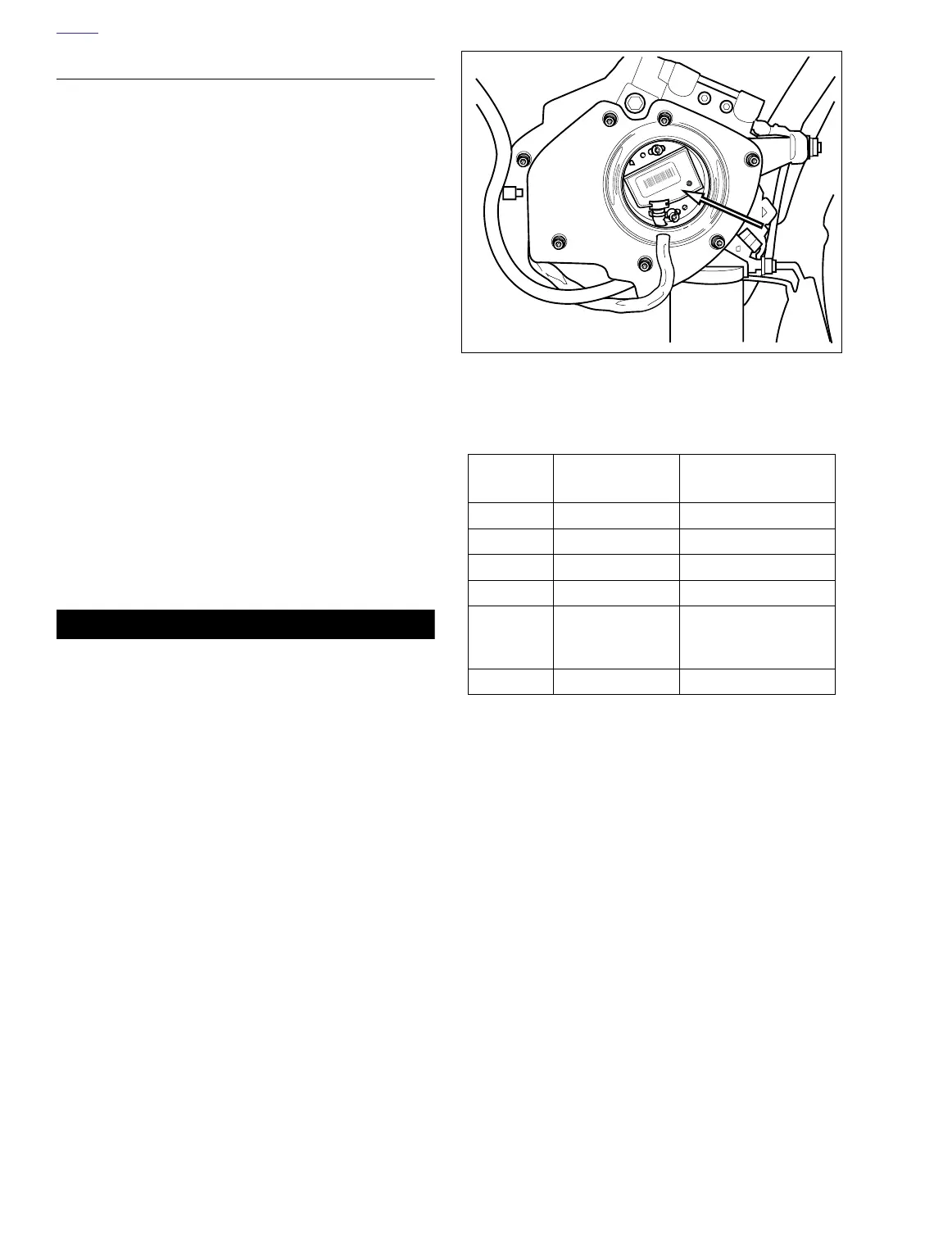
Figure 7-20. Ignition Module and Cam Position Sensor
Table 7-17. Ignition Module Connector [10]
CHAMBER
NUMBER
WIRE COLOR FUNCTION
1 White/Black To Ignition Switch
2 Violet/White To TP Sensor
3 Violet/Orange To Auto-Enrichener
4 Pink To Coil
5
*Lt Green/Grey
[10A]
*Tan/Yellow [10B]
To Sidestand Interlock
6 Black Ground
a0288x7x