7-24 2007 Buell P3: Electrical
HOME
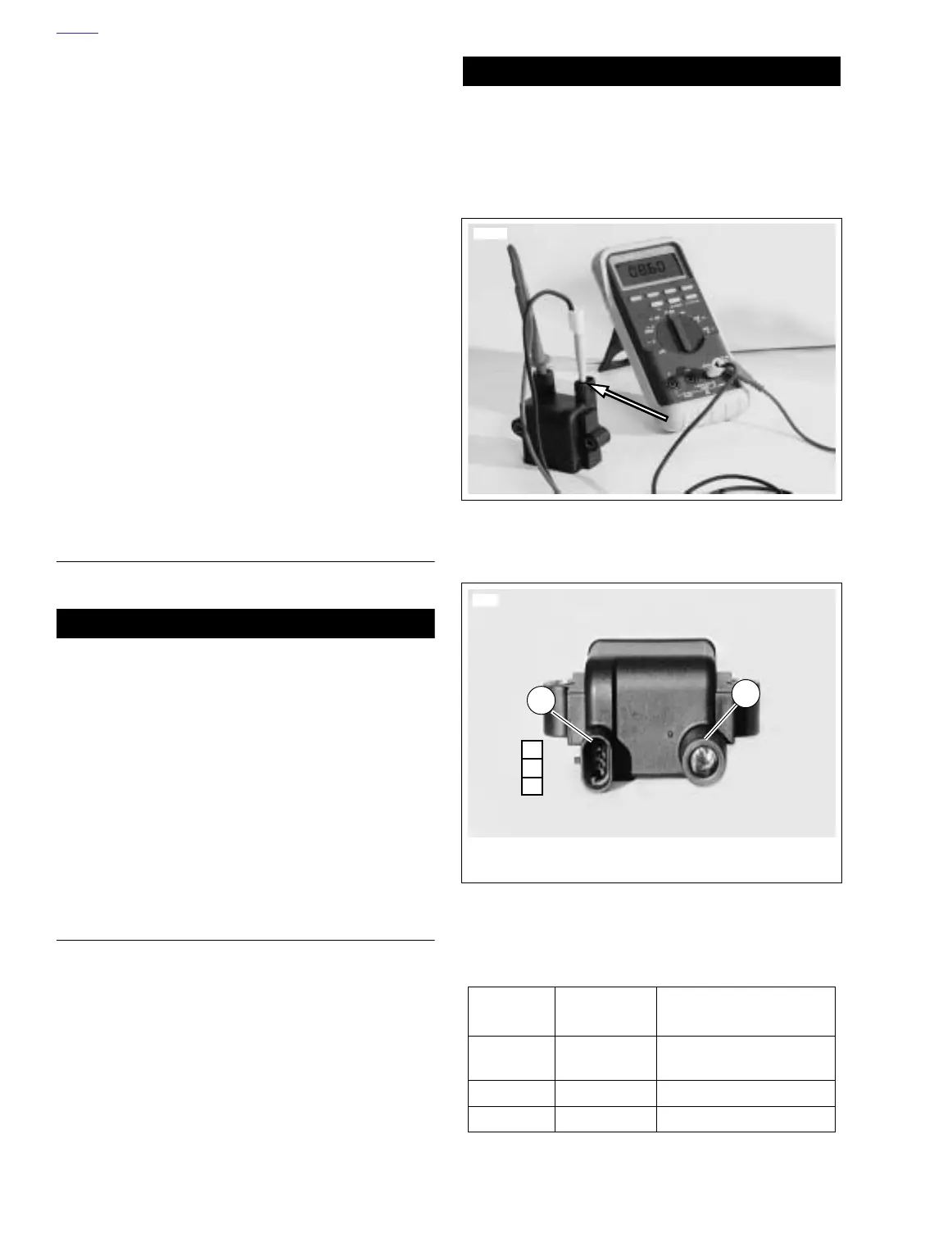
Ignition Coil Secondary Circuit Test
1. Remove ignition coil.
2. Set ohmmeter scale to RX1K.
3. See Figure 7-26. Using gray female probes and patch
cord from TEST CONNECTOR KIT (Part No. HD-41404),
place multimeter wires on secondary coil windings. See
7.9 IGNITION COIL.
4. Check for secondary coil winding resistance.
a. Normal resistance range is 7720-9440 ohms.
b. See Test Results if resistance is not within normal
operating range.
Test Results
1. A low resistance value indicates a short in the coil wind-
ing. Replace coil.
2. A high resistance value might indicate that there is some
corrosion/oxidation of the coil terminals. Clean the termi-
nals and repeat resistance test. If resistance is still high
after cleaning terminals, replace coil.
3. An infinite ohms (∞ or no continuity) resistance value
indicates an open circuit (a break in the coil winding).
Replace coil.
REMOVAL
1. Remove seat. See 2.28 SEAT.
11WARNING1WARNING
To prevent accidental vehicle start-up, which could
cause death or serious injury, disconnect negative (-)
battery cable before proceeding. (00048a)
2. Disconnect negative battery cable from battery terminal.
3. Remove fuel tank cover. See 4.2 FUEL TANK COVER/
FUEL TANK.
4. Remove left side cover.
5. See Figure 7-24. Disconnect spark plug cable from coil
plug post.
6. See Figure 7-27. Disconnect coil connector [83].
7. Remove two screws and washers and coil.
INSTALLATION
1. See Figure 7-24. Apply Loctite 243 (blue) to threads of
two mounting screws.
2. Attach coil to frame with screws and washers (1). Tighten
to 48-72 in-lbs (5-8 Nm).
3. Attach coil connector [83].
4. Connect spark plug cable to ignition coil.
5. Attach left side cover.
6. Install negative battery cable to battery terminal. Tighten
fastener to 72-96 in-lbs (8-11 Nm).
7. Install fuel tank cover. See 4.2 FUEL TANK COVER/
FUEL TANK.
11WARNING1WARNING
After installing seat, pull upward on front of seat to be
sure it is in locked position. While riding, a loose seat can
shift causing loss of control, which could result in death
or serious injury. (00070a)
8. Install seat. See 2.28 SEAT.
Figure 7-26. Ignition Coil Secondary Resistance Test at
Terminal C
Figure 7-27. Coil Viewed From Bottom
Table 7-18. Coil Connector [83]
CHAMBER
NUMBER
WIRE COLOR FUNCTION
A
White/Black (+) To Right Handlebar
Switch
B Pink (-) To Ignition Module
C Black Ground
7798
7799
1. Connector [83A], with terminals C, B and A
2. Spark plug post
C
B
A
1
2