18.5 Pulse measurements
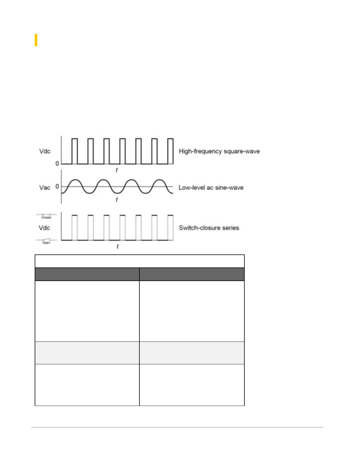
The output signal generated by a pulse sensor is a series of voltage waves. The sensor couples its
output signal to the measured phenomenon by modulating wave frequency. The data logger
detects the state transition as each wave varies between voltage extremes (high-to-low or low-
to-high). Measurements are processed and presented as counts, frequency, or timing data. Both
pulse count and period-average measurements are used to measure frequency-output sensors.
For more information, see Period-averaging measurements(p. 101).
The data logger includes terminals that are configurable for pulse input as shown in the following
image.
Table 18-2: Pulse input terminals and the input types they can measure
Input type Pulse input terminal
High-frequency
C (all)
SE 1-4
P_SW
P_LL
Low-level AC
P_LL
Switch-closure
C (all)
P_SW
18. Measurements102