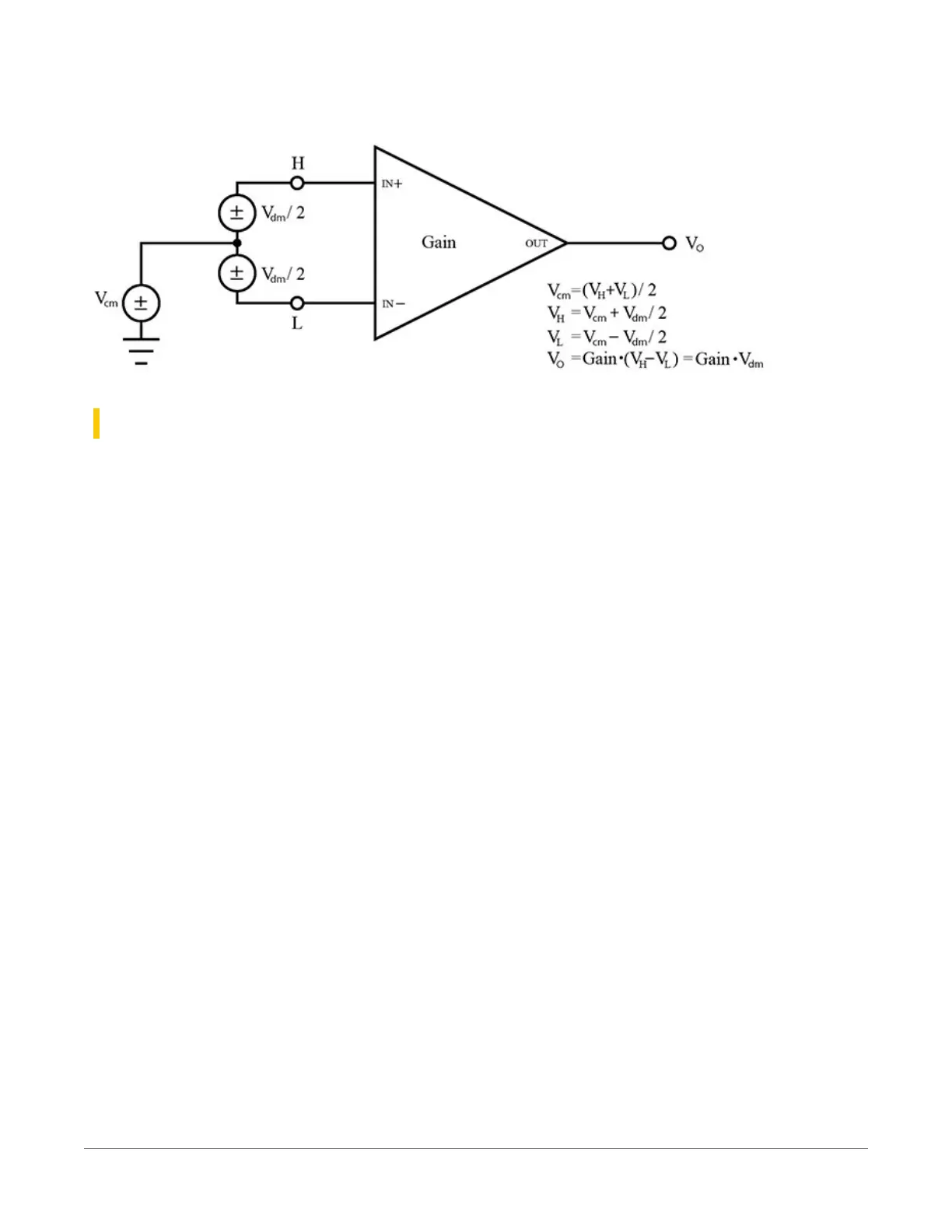
So, V
cm
= (V+ + V–)/2 or the voltage remaining on the inputs when V
dm
= 0. The total voltage on
the V+ and V– inputs is given as V
H
= V
cm
+ V
dm
/2, and V
L
= V
cm
– V
dm
/2, respectively.
22.11.4 Filtering to reduce measurement noise
The data logger applies an adjustable filter to analog measurements, reducing signal
components at selected frequencies. The following figures show the frequency response of the
filters applied when the first notch frequency (fN1) is set to 4000, 400, or 50/60 Hz, respectively.
Note that the same filter is applied when fN1 is set to either 50 or 60 Hz, simultaneously filtering
both 50 and 60 Hz signal components. Commonly, fN1 is set at 50 or 60 Hz in order to filter 50
or 60 Hz signal components, reducing noise from ac power mains.
Filtering comes at the expense of measurement time. The time required for filtering is 0.5 ms
when fN1 is set to 4000 Hz, 6.226 ms when fN1 is 400 Hz, and 49.812 ms when fN1 is set to
either 50 or 60 Hz. Random noise in the measurement results decreases, while measurement
time increases, as fN1 is set to smaller values. The total time required for a single result includes
settling + filtering + overhead.
A faster filter may be preferred to achieve the following objectives:
l
Minimize time skew between successive measurements Avoiding time skew(p. 174).
l
Maximize throughput rate.
l
Maximize life of the data logger power supply.
l
Minimize polarization of polar sensors such as those for measuring conductivity, soil
moisture, or leaf wetness. Polarization may cause measurement errors or sensor
degradation.
l
Improve accuracy of an LVDT measurement. The induced voltage in an LVDT decays with
time as current in the primary coil shifts from the inductor to the series resistance; a long
integration may result in most of signal decaying before the measurement is complete.
22. Tips and troubleshooting193