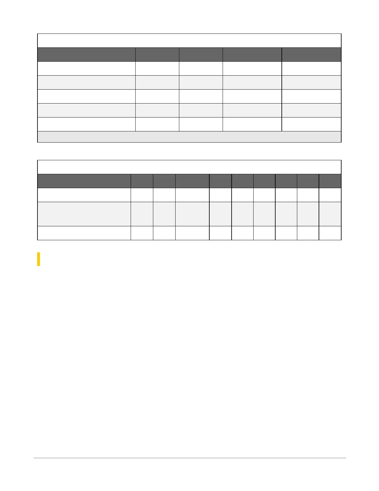
Table 5-5: Communications terminal functions
C1 C2 SE1-3 RS-232
SDI-12 ✓ ✓
RS-232 ✓
RS-232 0-5V ✓ ✓
GPS Time Sync ✓ ✓ ✓
GPS NMEA Sentences Rx Rx Rx
Communications functions also include Ethernet (CR310 only) and USB
Table 5-6: Digital I/O terminal functions
C1 C2 P_SW SE1 SE2 SE3 SE4 SE5 SE6
General I/O ✓ ✓ ✓ ✓ ✓ ✓ ✓
Pulse-Width Modulation
Output
✓ ✓ ✓ ✓
Interrupt ✓ ✓ ✓ ✓ ✓
5.1 Power input
The data logger requires a power supply. It can receive power from a variety of sources, operate
for several months on non-rechargeable batteries, and supply power to many sensors and
devices. The data logger operates with external power connected to the green BAT and/or CHG
terminals on the face of the wiring panel. The positive power wire connects to +. The negative
wire connects to -. The power terminals are internally protected against polarity reversal and high
voltage transients.
In the field, the data logger can be powered in any of the following ways:
l
10 to 18 VDC applied to the BAT + and – terminals
l
16 to 32 VDC applied to the CHG + and – terminals
To establish an uninterruptible power supply (UPS), connect the primary power source (often a
transformer, power converter, or solar panel) to the CHG terminals and connect a nominal 12
VDC sealed rechargeable lead-acid battery to the BAT terminals. See Power budgeting(p. 157)
for more information.
5. Wiring panel and terminal functions10