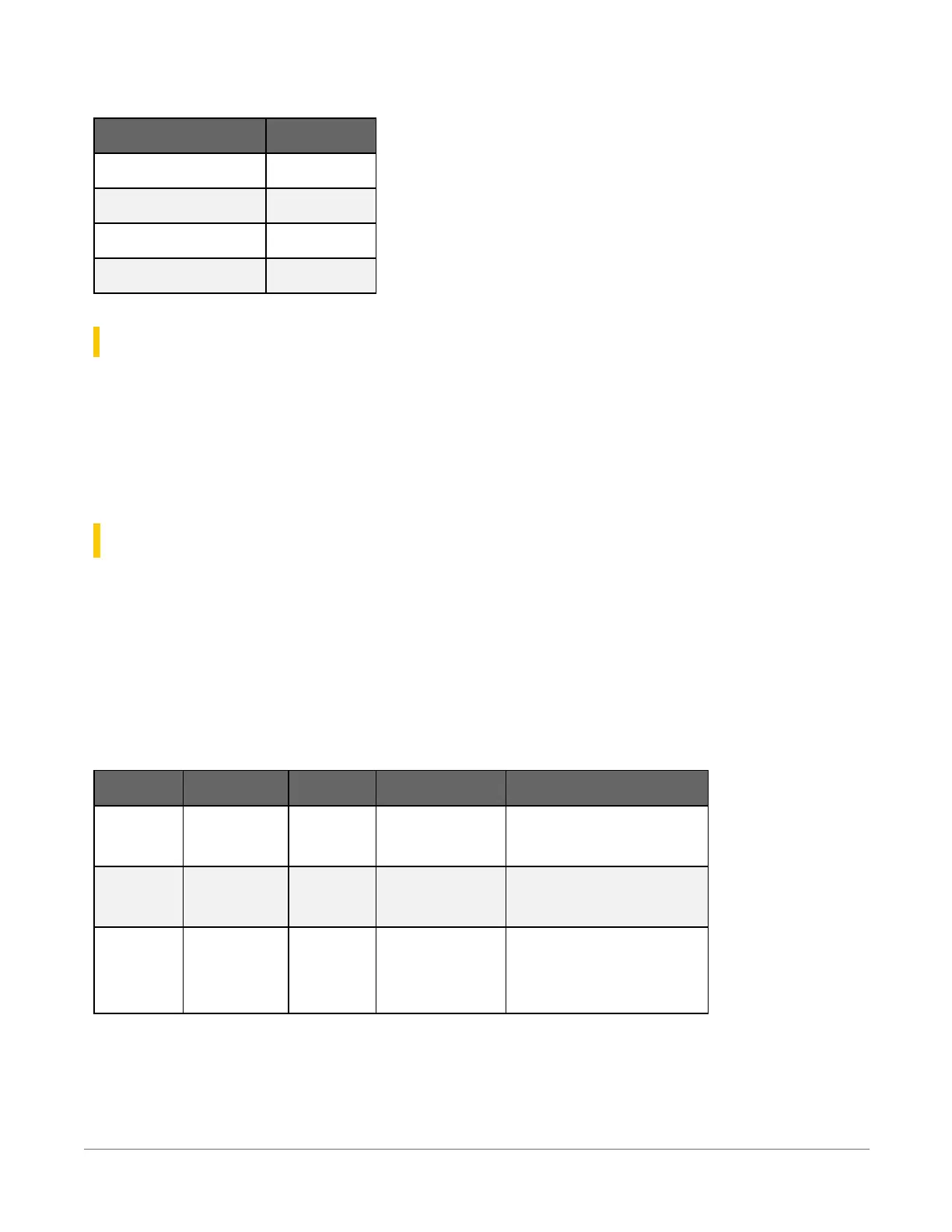
Low-Level AC Pulse Input Ranges:
Sine wave (mV RMS) Range (Hz)
20 1.0 to 20
200 0.5 to 200
2000 0.3 to 10,000
5000 0.3 to 20,000
24.6.4 Quadrature input
Terminals: SE1 and SE2 or C1 and C2 can be configured as digital terminal pairs to monitor the
two sensing channels of an encoder.
Maximum Frequency: 2.5 kHz
See Pulse measurements(p. 102) for additional information.
24.7 Digital input/output specifications
Up to seven terminals may be configured for digital input or output (I/O).
Terminals:
l
SE1-SE4
l
P_SW
l
C1-C2
Digital I/O Voltage Levels:
Terminal High State Low State Current Source Maximum Input Voltage
C1
C2
5.0 V output
3.3V input
0 V 10 mA at 3.5 V –10 V, +15 V
SE1
SE2
3.3 V 0 V 100 µA at 3.0 V –6 V, +9 V
SE3
SE4
P_SW
3.3 V 0 V 100 µA at 3.0 V ±17 V
See also Power output(p. 12) and Pulse measurement specifications(p. 247).
24. CR300 series specifications248